Disc Centrifuge Manual
Table of Contents
Manual Overview
Operation Manual of Disc Centrifuge
Contents
1. Safety Instructions
2. Fundamentals
3. Operating Procedures
4. Fault Dectection

In order to make this information clear and understandable, only foreseeable situations have been considered. Therefore, warnings cannot be provided for situations arising from improper use of machinery and tools that result in unintended damage.
1. Safety Instructions
The centrifuge utilizes high-speed rotating components. This means:
-High kinetic energy
-Extremely large forces generated
-Extended downtime
Manufactured with precision tolerances, the rotating components undergo careful balancing to minimize unnecessary vibrations that could lead to malfunctions. Material characteristics are thoroughly considered in the design process to withstand stress and fatigue.
The centrifuge is specifically designed for certain separation purposes (liquid type, rotational speed, temperature, density, etc.) and must not be used for any other purposes.
Incorrect operation and maintenance can result in the accumulation of deposits, weakening material strength, leading to imbalance during machine operation, and causing severe equipment damage and/or injury to personnel.
Therefore, the following basic safety instructions should be followed:
-Use the centrifuge only for its designated purpose and within the specified parameter range.
-Strictly adhere to the installation, operation, and maintenance instructions.
-Ensure that personnel involved are competent in their roles and possess extensive knowledge in maintenance and operation, especially in emergency shutdown procedures.
-Use only genuine parts and specialized tools provided by our company
![]() Fragile Danger:
Fragile Danger:

When connecting the power cable, always check the rotation direction of the motor. If the direction is incorrect, screws on critical rotating components may loosen.

If excessive vibration occurs, stop the centrifuge and maintain liquid in the drum during the deceleration process.
 Only use the centrifuge for its designated purpose within the specified parameter range.
 Check whether the transmission ratio/belt pulley ratio corresponding to the applied power frequency is correct. If incorrect, subsequent overspeed may lead to serious malfunctions.
 If the centrifuge is driven by a variable frequency drive, ensure that the frequency does not exceed the allowed maximum to prevent serious malfunctions at excessive speeds. The wear on the large locking ring thread must not exceed safety limits. The distance between the Φ mark on the locking ring and its corresponding Φ mark should not exceed the specified distance.
Welding or heating the rotating components may severely impact the strength of the material.

Regularly inspect for damage caused by corrosion and erosion. If the process or cleaning fluids are corrosive or erosive, frequent checks are necessary.
Pinch Hazard:
Before approaching internal components of the machine or initiating any disassembly tasks, ensure that rotating parts have completely stopped. If there is no braking function, the coasting time may exceed two hours.
 To prevent accidental start-up, shut off and lock the power source before commencing any disassembly work.
Before starting, assemble the machine completely. All covers, connections, and protective devices must be in place.
 Electrical Hazard:
Adhere to local regulations regarding electrical installation and grounding.

To prevent accidental start-up, shut off and lock the power source before commencing any disassembly work.
![]() Crushing Hazard:
Crushing Hazard:
Use appropriate lifting tools and follow lifting instructions.
Do not work underneath a suspended load

Noise Hazard: Use ear protection in noisy environments.
Burn Hazard: Lubricating oil, machine components, and various machine surfaces can become hot and may cause burns. Wear protective gloves.

![]() Irritation Hazard:
Irritation Hazard:
When using chemical cleaners, always follow general guidelines and the supplier's recommendations regarding ventilation and personal protective measures.

Use lubricants in various situations.
Scratch Hazard:
Sharp edges, especially on the drum disc and threads, may cause scratches. Wear protective gloves.

![]() Projectile Hazard:
Projectile Hazard:
During disassembly and assembly, there is a risk of snap rings and springs unexpectedly flying out. Wear safety goggles.
 Health Hazard:
When handling friction blocks/pads, there is a risk of inhaling harmful dust. Use a dust mask to ensure that no dust is inhaled.

1.1 Warning Sign
Please pay attention to the safety instructions in this manual. The following are definitions for the three levels of warning signs (indicating the risk of personal injury) used in this document.
 "Danger" indicates an imminent hazardous situation that, if not avoided, will result in death or serious injury.

"Warning" indicates a situation with potential hazards, and if not avoided, could result in death or serious injury.

"Caution" indicates a situation with potential hazards, and if not avoided, could result in minor or moderate injuries.

"Note" indicates a situation with potential hazards, and if not avoided, could result in property damage.
1.2 Personnel Requirements

Only personnel who are technically proficient or under supervision are allowed to operate the machine, such as operators and maintenance personnel.
Technically Proficient Personnel: Individuals in this category possess relevant technical knowledge or extensive experience, enabling them to be aware of risks and avoid potential dangers posed by electrical/mechanical aspects.
Supervised Personnel: Individuals in this category receive thorough guidance or supervision from technically proficient personnel, allowing them to be aware of risks and avoid potential dangers posed by electrical/mechanical aspects.
In some cases, it may be necessary to employ personnel with special skills, such as electricians and other specialists. In certain situations, certification may be required for individuals with similar job experience, in accordance with local regulations.
2. Fundamentals of Centrifuges
 Gravity Sedimentation
2.1 Basic Principles of Separation
2.1.1 Introduction to the Purpose of Separation
-Remove liquid from solid particles.
-Separate two immiscible liquids with different densities, while eliminating any solid substances.
-Purify solid particles from a liquid.
2.1.2 Gravity Separation

The sedimentation in a container with an outlet makes it possible to separate light liquid from heavy liquid.
-When large particles in a liquid mixture settle to the bottom of a stationary container under the influence of gravity, the liquid mixture gradually clears.
-Heavier liquids and solids sink while lighter liquids float.
-Continuous separation and settling can be achieved in settling tanks with multiple outlets, arranged according to the different densities of liquids.
-Heavier particles in the liquid mixture settle, forming a sediment layer at the bottom of the settling tank.
2.1.3 Centrifugal Separation

-In a rapidly rotating drum, gravity is replaced by centrifugal force, which is many times greater.
-Separation and sedimentation continue at a very fast pace.
-The separation achieved by centrifugal force inside the drum in a few seconds is equivalent to what may take many hours under gravity in a settling tank.
2.1.4 Separation Temperature
-For certain types of process liquids, a higher separation temperature typically increases processing efficiency. Temperature affects the viscosity and density of materials, so consistency in temperature should be maintained during the separation process.
Viscosity
Low viscosity is advantageous for separation. Heating can reduce viscosity.
 High viscosity (low temperature)
 Low viscosity (high temperature)
Density Difference
The greater the density difference between two liquids, the easier the separation. Density difference can be increased by heating.
 High Density (low temperature)
2.2 Design and Function
2.2.1 Application
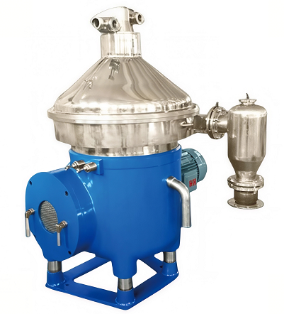
The disc centrifuge is a high-speed centrifuge used in industrial applications. It is a partially sludge-discharging separator.
The centrifuge must be installed with control and monitoring equipment for the separation process.

 Never use the centrifuge to separate other
liquids or materials that contradict the originally specified liquid characteristics. If your requirements change, be sure to contact our representative before making any modifications.
The separator consists of a product separation section and a drive section. It is driven by an electric motor (8). The flange-mounted electric motor is installed on the frame, as shown in the diagram. The frame base (6) serves as a vibration damper.

The bottom of the separator includes a lateral drive unit (4), a drive shaft with an elastic coupling (7), a worm wheel (5), and a vertical drive unit (3).
1.Inlet and Outlet Device 2.Drum 3. Vertical Drive Unit for Drum Shaft
4. Lateral Drive Unit 5.Worm Wheel 6. Frame Base
7.Elastic [Flexible] Coupling 8.Electric Motor 201.Inlet for Unseparated Liquid
220.Outlet for Separated Light Liquid Phase 221.Outlet for Separated Heavy Liquid Phase 222.Precipitate Outlet
The bottom also contains an oil sump for lubricating the worm wheel.
The upper part of the separator includes the product process section, the drum (2), and the inlet/outlet device (1).
The liquid is separated into two phases in the centrifuge drum, namely the light liquid phase and the heavy liquid phase. Additionally, heavier precipitates are also separated from the liquid.
The drum is installed at the top of the vertical shaft and rotates at high speed. The drum also includes an emission mechanism to discharge precipitates from the drum.
Figures (201, 220 & 221) illustrate the inlet for the liquid to be separated, as well as the outlets for the separated liquids, along with the corresponding joint numbers.
Detailed descriptions of these numbered connections and basic dimension diagrams are available in the installation manual. This information describes and illustrates the inlet and outlets of the centrifuge.
2.2.3 Mechanical Power Transmission

1. Electric Motor (Note! Motor specially designed for centrifuges with a flexible coupling and equipped with a thermal resistor)
2. Friction Coupling 3.Worm Wheel Shaft 4. Top Bearing 5. Drum Main Shaft 6. Worm 7.Worm Wheel
The electric motor (1) rotates the drum through a flexible coupling (2) and a worm gear (6, 7). The worm gear allows the drum speed to match the motor speed.
The worm gear has a transmission ratio that can increase the drum speed several times compared to the motor speed. For precise transmission ratios, please refer to the "Technical Data" section in the
installation manual.
To reduce bearing wear and transfer vibrations from the drum to the frame and base, the top bearing
(4) of the drum main shaft (5) is mounted in a bearing housing with rubber cushioning.
The worm gear operates in a lubricating oil bath. Bearings on the main shaft and the worm wheel shaft (3) are lubricated by oil splashing as the worm gear rotates.
2.2.4 Electric Motor
Variable frequency drive motor, maximum 60Hz
The centrifuge is directly driven by an electric motor, and therefore, the motor must withstand long start times. For this purpose, the centrifuge is equipped with a variable frequency drive motor.
This type of motor is similar to standard three-phase motors, but the extended start times are controlled by a frequency inverter.
 Thermistor
2.2.5 Brake
The centrifuge is equipped with a brake to stop the centrifuge. The use of the brake reduces the delay of the drum and allows for a quick stop beyond the critical speed.
The brake lining acts on the outer side of the brake drum.
 Brake Action (1) and Release Action (2) of the Brake
2.2.6 Sensors and Indicators (Optional)
Vibration Sensor (1)

This sensor operates as a vibration velocity type. The vibration signal must be converted into a usable signal (meeting the required specifications) by a dedicated converter in the control system.
Appropriate measures must be taken when either of the two limit values is exceeded. The two levels are acceptable vibration warning and safe shutdown in the case of extreme imbalance. Detailed descriptions of these two vibration levels are provided in the Interface Description section of the installation manual.
Speed Sensor (2)
The proximity-type speed sensor is inductive, providing a set number of pulses for each rotation of the motor shaft. The installation manual specifies the pulse count in the connection list section. The drum speed can also be calculated using the transmission ratio and the motor shaft's revolutions per minute.
During normal operation, the speed is allowed to vary within the speed limit range, which is described in the Interface Description section of the installation manual.
Lid Interlock Switch (3), Optional
The centrifuge's lid is equipped with an interlock switch. When the lid is closed, the interlock circuit of the control system is engaged, allowing the centrifuge to start.

1. Centrifugal pump casing cover 2. Small locking ring 3. Drum cover
4. Upper disc 5. Drum disc assembly 6. Drum body
7. Drum cover seal ring 8. Precipitate channel 9. Precipitate space
10. Open chamber 11. Closed chamber 12. Feeding ring
13. Sliding operating disk 14. Spring bracket 15. Operating liquid equipment
16. Spring 17. Valve plug 18. Nozzle
19. Drain channel 20. Sliding drum chassis 21. Conical distribution plate
22. Large locking ring 23. Distributor 24. Inlet pipe
25. Liquid level ring 26. Clear liquid centrifugal impeller 27. Clear liquid zone
28. Frame cover 29. Height adjustment ring 30. Discharge outlet cover
201. Inlet for the unseparated liquid 220. Outlet for the separated light phase liquid
221. Outlet for the separated heavy phase liquid 372. Slag water inlet
376. Sealed water inlet
 Centripetal pump impeller (discharge pump)
The inlet and outlet device include the following components:
Inlet for the unseparated liquid (201). It consists of a curved pipe and an inlet pipe (24).
Outlets for the separated liquid (220, 221). The outlet for the heavy phase liquid (221) is composed of the centrifugal impeller (26). The centrifugal impeller is located in the centrifugal pump chamber
(27) at the top of the drum.
The centrifugal pump is a type of pump where the impeller is stationary, and it is immersed in the rotating liquid, pumping the liquid out.
To prevent the entry of gas into the separated liquid, it is crucial for the impeller of the centrifugal pump to maintain a certain range of outlet back pressure.
The inlet and outlet device is fixed on the frame cover (28) of the centrifuge. The height adjustment ring (29) is secured between the top of the frame cover and the discharge outlet cover (30), determining the height of the centrifugal pump impeller (26).
The structure of the centrifuge drum with a sediment discharge mechanical device is as follows:
The drum body (6) and drum cover (3) are fixed together with a large locking ring (22). Inside the drum, there is a distributor bottom cone (21), distributor (23), and a set of separating blades (5). The drum cover keeps the separating blades in a compressed state. The sliding drum chassis (20) at the bottom of the drum is a separable component.
At the top of the drum, there is a cover for the centrifugal pump chamber (1), and the cover for the centrifugal pump chamber is fixed on the drum cover through a small locking ring (2).
The precipitate space (9) is the space between the sliding drum chassis and the drum cover at the outer periphery of the drum. This space is sealed by the sliding drum chassis (20) and the drum cover (3) through sealing rings (7).
Sediment Discharge Mechanical Device
After a determined time interval chosen by the operator, the sliding drum chassis descends to discharge the sediment from the drum.
The sediment discharge mechanical device, controlling the sliding drum chassis, consists of a sliding operating disk (13) and operating liquid equipment (15). Passive components include the feeding ring (12), nozzle (18), and discharge valve plug (17). The operating liquid equipment beneath the drum provides operating liquid (372 & 376) for the discharge structure.
2.2.8 Cyclone
When discharging accumulated sediment from the centrifuge drum, the discharge speed is extremely high. To prevent the reaction force acting on the centrifuge, it is necessary to reduce the speed before discharging the sediment from the centrifuge. This step is carried out within the discharge cyclone (A). While the sediment rotates inside the cyclone, its speed gradually decreases due to the influence of wall friction until its speed is reduced enough to be discharged from the outlet (222) by gravity.
 Cyclone(A)
|
|
|
When sediment is suddenly discharged into the cyclone, positive pressure shock waves occur inside the cyclone, and corresponding negative pressure impacts occur in the drum cover.
This is caused by a certain amount of material suddenly moving from one place to another.
After discharge, the airflow returning from the cyclone to the drum cover will compensate for the pressure. The returning gas may contain some sediment, potentially causing sediment accumulation
on the inner surface of the drum cover. Some shock pressure may also be discharged through the outlet (222) into the external sediment receiving system, which could damage the system or disperse suspended particles into the surroundings.
To reduce pressure impacts, the cyclone is equipped with a vent (543) at the top.
2.3.1 Normal separation (this picture shows three-phase separation)

Drum
The diagram inside the box refers to the illustration explained on page 23.
Unseparated liquid enters the interior of the drum through the inlet pipe (24) and reaches the periphery of the drum through the distributor (23). When the liquid reaches the slots at the bottom of the distributor, it rises through the channels formed by the separating blade assembly. Under the action of centrifugal force, the liquid is evenly distributed in the space between the blades of the drum, where light and heavy liquids are separated from each other.
The heavy liquid phase and all sediment descend along the drum discs to the edge of the drum, where sediment accumulates in the precipitate space (9). The heavy liquid phase moves along the top disc (4) to the neck and blades of the drum cover, and through the gravity disc – outward path (shown in dark in the previous page's diagram), it is discharged from the drum. The light liquid phase moves toward the center of the drum along the separating blades of the drum, and it is pumped out of the drum through the small holes in the impeller of the centrifugal pump and the neck of the top separating blade – inward path (shown in light in the previous page's diagram).
The discs determine the interface position within the drum (see the diagram below).
For information on correctly selecting the density rings, refer to page 45 under "3.1.3 Selection of Density Rings."

Specific gravity ring

Interface location (1)
An interface (1) will inevitably form between the light liquid phase and the heavy liquid phase within the drum. To achieve the desired separation efficiency, this interface must be maintained in the correct position, specifically between the separating blade assembly and the outer edge of the top blade. If the interface moves beyond the outer edge of the top blade, the
liquid seal will be disrupted, and the light liquid phase will be discharged along with the heavy liquid phase. If the interface is inside the separating blade assembly, it will have a severely negative impact on the separation efficiency.
The interface position can be adjusted by changing the pressure balance of the liquid phase within the centrifuge, achieved by altering the wall density ring. Therefore, the centrifuge will be delivered with density rings of different diameters to provide this capability.
2.3.2 Sediment Discharge Cycle
The schematic diagram of the sediment discharge cycle described here is a general representation and may not fully correspond to the actual drum configuration.
Closed drum (normal operation):
Solid material is discharged from the centrifuge drum through some elongated holes or openings in the drum wall. Between discharge intervals, these outlets are closed by a large sliding valve known as the sliding drum chassis (20), which forms an inner bottom within the separation space. The hydraulic pressure acts below the sliding drum chassis, pushing it up against the sealing ring (8).
The sliding operating disk (14) is pushed upward by a spring (17), sealing the discharge channel (19) with the valve plug (18).
As the drum rotates, the liquid pressure increases with the distance from the axis of rotation due to the centrifugal force. Operating liquid (376)* applies an upward pressure to the sliding drum chassis (12), which exceeds the symmetric force acting downward from the process material liquid because the pressured area below the sliding drum (radius R1) is larger than the pressured area above (radius R2).
The operating liquid (376) is transported to the bottom of the drum through centrifugal pump equipment. The centrifugal pump automatically compensates for leaked or evaporated operating liquid, maintaining a constant level of operating liquid (radius R3). This acts as a pumping effect, balancing the static pressure of the water supply. During sediment discharge, operating liquid is continuously supplied, as described in the subsequent diagrams of the discharge cycle (see).

Drum open, discharge in progress.
The inlet pressure of the discharged liquid (372) is higher than that of the operating liquid and can be sustained for 2 seconds (this is sufficient for completing one discharge). The liquid flows into the upper chamber (radius R4) and directly enters the open chamber (11) on the top of the sliding operating disk (14) through a channel.
The increased pressure in the open chamber is greater than the pressure of the spring, causing the sliding operating disk to press downward. The valve plug (18) will open (explained on the next page), and the operating liquid is discharged through the discharge channel (19) via the upper nozzle (10).

When the valve plug (18) opens, a large amount of operating water is discharged, and the supply of water is insufficient. The pressure below the sliding drum chassis (20) decreases, causing the drum chassis to be pressed downward. This action opens the sediment discharge outlet (7) in the drum wall, allowing sediment to be discharged.
All operating liquid flows out from the space below the sliding drum chassis, collected by the feeding ring (13) through the open discharge channel (19).
When the space above the sliding operating disk (14) is filled, liquid flows from the notch (28) on the sliding operating disk to the space between the bottom of the sliding operating disk and the bottom of the feeding ring, commonly referred to as the closed chamber (12). Operating liquid and discharge liquid are continuously discharged through the nozzles (10) on both sides.

After discharge, the drum closes, cutting off the supply of discharge liquid (372). Thus, there is a hydraulic semi-automatic operation within the closed chamber (12). Water pressure forces the sliding operating disk to move equally either upward or downward, and the spring causes the sliding operating disk to move upward.
The discharge channel (19) is closed by the discharge valve plug (18), and the increased pressure of the operating liquid (376) pushes the sliding drum chassis (20) upward. The drum closes, completing the sediment discharge. The operating liquid collected by the feeding ring freely flows out through the nozzles in the ring wall.
2.4.1 Viscosity and Density
Refer to page 17, "2.1.4 Separation Temperature."
2.4.2 Interface Position

A. Correct Interface Position
B. Incorrect Interface Position — Liquid Seal Disruption
C. Incorrect Interface Position — Poor Separation Efficiency
1. Density Difference and Flow Rate
If the density difference between phases is small and the flow rate is high, the liquid interface is closer to the drum edge compared to a situation where the density difference between phases is large.

Small Density Difference/High Flow Rate Large Density Difference/Low Flow Rate
2. Density Rings
To correct the effects caused by the factors mentioned above, adjustments can be made by changing the heavy phase outlet, for example, by swapping density rings.
Using a density ring with a larger aperture can move the interface toward the drum edge, while using a gravity disc with a smaller aperture will move the interface toward the drum center.

A. Density Ring with a Large Aperture
B. Density Ring with a Small Aperture
3. Supranormal Back Pressure
Excessive back pressure at the light liquid phase discharge outlet hinders the discharge of the light liquid phase. The interface position will move outward toward the drum edge. The result is an incorrect interface position, which may lead to the disruption of the liquid seal.
A. Supranormal Back Pressure
B. Normal Back Pressure
Circular and smooth sediment particles (A) are easier to separate compared to irregular sediment particles (B).

1. Large particles
2. Small particles
A. Smooth particle
B. Irregular particles
x. Throughput
y. Particle size
In cases of rough handling, where materials are pumped, particle breakage may occur, resulting in a slower separation process. Larger particles (1) are easier to separate than smaller particles (2), even if their densities are the same.
2.4.4 Phase Ratios
An increase in the quantity of heavy phase in the processed liquid affects separation efficiency under the premise of the optimal conveying capacity of the separation blade assembly. By reducing the flow rate, the increase in the concentration of the processed liquid can be counteracted to restore optimal separation efficiency.
2.4.5 Flow Rate
The flow rate depends on the separation capacity and the sediment space volume of the drum, and is related to the concentration, particle size, density, and viscosity of the processed liquid.
2.4.6 Characteristics of Sediment
Certain types of sediment may agglomerate and accumulate in the drum, reducing separation efficiency. In such cases, cleaning is necessary after separation.
 Sediment space inside the separator drum
2.4.7 Separating Blade Assembly
Neglecting the separating blade assembly—including deformed blades or blades covered with sediment—weakens the separation efficiency.
2.4.8 Back Pressure Adjustment
The correct back pressure depends on the flow rate of the processed liquid. Please refer to the "Technical Data" section in the installation manual for information on the relationship between back pressure and flow rate.
 Setting the correct back pressure is important
For optimal results when the distributor is not leaking, it is best to maintain the back pressure as high as possible.
Be cautious not to choose excessively high back pressure,
Setting the correct back pressure is important
as it may pose the risk of leakage from the distributor (unseparated process liquid) into the centrifugal pump chamber (separated) or leakage from the centrifugal pump chamber to the frame cover.
However, if you want to avoid air mixing into the processed liquid (through the centrifugal pump chamber), too low back pressure is also not suitable.
2.4.9 Sediment Discharge
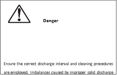
If the solid content in the processed liquid is high, shorter slag discharge intervals are required. Overfilling the slag chamber space will reduce the quality of the separated liquid. However, it is essential to control the slag discharge time within the specified shortest and longest time ranges, as outlined in the "Technical Data" section of the installation manual. How to calculate the slag discharge interval is described in the "2.5 Sediment Discharge Interval" section on page 38.

Do not overfill the sediment space
This separator operates as a partially controlled sludge discharge type, discharging a fixed volume of sediment. The discharge volume is approximately 70% of the external volume of the blade assembly. The correct time to choose for the discharge interval depends on the prevailing conditions since various factors influence the accumulation and hardening of sediment during the discharge interval. However, it is crucial to control the discharge interval within the specified shortest and longest time ranges, as outlined in the technical data section.
A prolonged sediment discharge interval may lead to sediment accumulation and solidification. During discharge, sediment may be unevenly flushed out, causing imbalance in the drum. If this imbalance is too severe, it can pose a serious risk of damage to the separator and injury to personnel.
t = Theoretical maximum time between two discharges, in minutes.
p = Percentage of sediment volume in the processed liquid.
Q = Flow rate in liters per hour.
V = Sediment volume (in liters or cubic decimeters).
Accumulation of sediment in the drum can be allowed if it does not compromise separation efficiency or if the solidification is not too firm. Typically, the maximum value for "V" should be three-quarters of the sediment space volume, calculated from the outer edge of the top separating blades. Refer to the technical data section in the installation manual for information on
sediment space volume.
If the solid content of the liquid is known or can be determined as a percentage of the liquid sediment volume (e.g., through centrifuge tubes), the sediment discharge interval can be selected according to the following formula.

1: Total volume of sediment space
V: Allowable sediment volume

1. Machine nameplate
Separator
Production Serial Number
Maximum Speed (Drum)
Speed Control Motor Shaft
Current Frequency
Total Weight of Separator
Recommended Motor Power
Date of Manufacture
Manufacturer
Website
Email Address
2. Safety Label Text on the Label:
**Warning**
Read the operation manual before installation, operation, and maintenance, considering the intervals for inspections.
Failure to strictly follow operational procedures may result in fatal damage.
If severe vibration occurs, immediately stop the separator and keep the drum filled with liquid during the shutdown.

If the drum is not filled with liquid, unbalanced vibrations will worsen.
Stop the rotation of the separator before any dismantling work.
3.Nameplate
4. Arrows

Indicate the direction of rotation for the horizontal drive unit.
5. Power Frequency
- **Back Pressure:** The pressure at the outlet of the centrifuge.
- **Counter Pressure:** See Back Pressure.
- **Density:** The mass per unit volume.
- **Intermediate Service (IS):** Inspection of the centrifuge drum, inlet/outlet, and operational fluid devices. Updating the seals in the drum's inlet/outlet and operational fluid devices.
- **Major Service (MS):** Inspection of the entire separator, including the bottom (including some items in intermediate service), updating seals, and bearings in the base portion.
- **Purification:** Separation of two mixed substances, liquid/liquid/solid, and immiscible liquid phases with different densities. Also involves removing solids with a density greater than that of the liquid. The primary goal is to purify the lighter liquid phase as much as possible.
- **Concentration:** Separation of two mixed substances, liquid/liquid/solid, and immiscible liquid phases with different densities. Also involves removing solids with a density greater than that of the liquid. The primary goal is to concentrate the heavier liquid phase as much as possible.
- **Precipitate:** Solid separated from a liquid.
- **Precipitate Discharge:** The ejection of precipitate from the centrifuge drum.
- **Throughput:** The quantity of process liquid supplied to the centrifuge per unit of time.
- **Viscosity:** The resistance to flow, hindering movement.
3.1.1 Introduction
These procedures outline the general steps to be followed before and during startup, as well as the operational and shutdown procedures for the centrifuge. They are prepared not only for the operators of the centrifuge but also for the designers of the centrifuge's controllers.
These instructions are specific to the centrifuge itself and are largely based on the information provided in the interface description chapter of the installation manual.
If the centrifuge is part of a system or module, these instructions must also be followed for that particular system or module.
3.1.2 Before the First Startup
Technical requirements and logical constraints related to the centrifuge connection are described in the following sections of the installation manual:
1. Technical Data
2. Basic Dimensional Drawings
3.Connection Interface List
4.Interface Description
5.Foundation Drawing
-Ensure that the machine is installed correctly, and the feed and discharge pipelines have been thoroughly flushed.
-Fill the lubricating oil in the gear seat until slightly above the centerline of the observation hole. Use the correct grade of lubricating oil. The centrifuge is delivered without oil.
 Fill the lubricating oil in the gear seat.
-Oil Capacity: Approximately 20 liters.
Refer to the recommended lubricating oil brand in the service and maintenance manual for the correct lubricating oil grade.

The centrifuge is delivered with a set of density rings.
The service and maintenance manual describes how to replace the density rings.
The diameter of the density ring determines the interface position of the light-to-heavy phase liquid in the centrifuge. The separation efficiency of each processing can be optimized by selecting the correct diameter.
A general rule for selecting density rings is that the perforated discs allow the light phase to be purified as much as possible.
When aiming to facilitate the separation of the light phase from the heavy phase, the interface position should be close to the edge of the drum.
For a more detailed description of the interface position, please refer to page 29, "Interface Position.
Density Ring Correct Size Calculation:

If the densities of the heavy and light phases are known, the hydraulic balance can be expressed as follows:
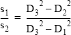
S1=Density of the light phase S2=Density of the heavy phase D1=Internal diameter of the outlet
For this centrifuge, it is determined by the internal diameter of the top disc spindle neck.
D2=External diameter of the outlet, which is the same as the hole diameter of the gravity disc D3=Diameter of the interface
3.1.4 Ready for Start
1. To achieve optimal separation efficiency, ensure that the drum is in a clean state.
2. Check if the bolts on the upper cover of the centrifuge are fully tightened.
 Leakage Check (No leakage allowed)
Check that all inlet and outlet connections are correctly attached and fully tightened. Ensure that hose connections and flange couplings are correctly assembled and tightened.
3. Check if the oil level is slightly above the center line of the sight glass. If necessary, fill with lubricating oil. Refer to the recommended lubricating oil brands section in the service and maintenance manual for details.

Note: During operation, the oil level should be slightly below the center line of the sight glass.
4. Confirm that the centrifuge brake is in the released state.
 Release the brake
3.1.5 Startup
1. Start the centrifuge.
2. Check the rotation direction of the drum; if the rotation direction is opposite, change it to clockwise.
 Vibrating Check
3.Check the vibration of the centrifuge. During the startup phase, momentary vibrations may occur when the centrifuge speed reaches the critical speed. This is normal and does not pose a danger. Try to understand the vibration characteristics of the critical speed mode.
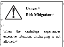
When excessive vibration occurs, keep the drum filled with liquid and stop the centrifuge. Before restarting the centrifuge, investigate the cause of the vibration and correct it. Excessive vibration may result from incorrect assembly or incomplete cleaning of the drum.
4.If possible, check the drive current of the motor starter to ensure that the centrifuge has reached full speed.
 When full speed is reached, reduce it to a set value.
During startup, the ammeter will display a maximum current, which will gradually decrease to a stable value, representing the normal operating current.
The time to reach full speed must not exceed the limits specified in the Technical Data section of the installation manual.
5.During normal operation, open the operating liquid valve (connected to 376) to close the drum.
3.1.6 Operation
1. Confirm that the outlets for both separated liquids (220 and 221) are fully open.
2. When the conditions for separating the liquids are met, open the inlet for the process liquid (201).
3.Adjust the flow to an optimal value.
4.Check the inlet and outlet pressures of the centrifuge.
For allowable pressure, temperature, and flow rates, refer to the Technical Data section in the installation manual.
5. Open the liquid discharge valve (372) to discharge the precipitate from the centrifuge until the discharge meets requirements.
The discharge interval should be adjusted based on the solid content of the material. Refer to page 38, "2.5 Interval for Discharging Precipitate," for calculating the discharge interval. Keep the discharge interval within the range specified in the technical data section of the installation manual.
6.Daily Inspection
The following inspection steps must be carried out daily:
a.Check all joints of pipes and hoses for any leaks.

Leakage Check (No leakage allowed)
b. Check the flow and pressure at the following connections:
Process liquid inlet (201)
Process liquid outlets for light and heavy phases (220 and 221) Operating liquid (375)
Cooling liquid (409 and 410)
Note:Refer to the installation manual's connection list section for accurate flow and pressure data.
 Check the oil level.
Note
During operation, the oil level should be slightly below the centerline of the sight glass. Too much or too little oil can potentially
damage the centrifuge bearings.
d.Check if the separator has any abnormal noise and vibration
 Vibrating check
When the vibration values are excessively high, the drum should be kept in a full liquid state, and the centrifuge should be stopped.
e. Check if the electric motor is overheated.
3.1.7 Normal Shutdown
1. Before stopping the centrifuge, empty all solids from the drum. If not emptied, manual cleaning must be done before the next start.
Repeat discharging until there are no more solids remaining in the drum. The drum must be filled with liquid during the discharge.
2. After discharging, inject liquid into the drum, fill the drum with liquid, and then stop the centrifuge.

During the shutdown process, it is essential to keep the drum consistently filled with liquid to prevent excessive vibration.
3. Brake Usage
3.1 Safe Shutdown
1. If the centrifuge begins to vibrate beyond the specified limit during operation, immediately shut down the electric motor of the centrifuge by pressing the safety stop button, bringing the centrifuge to a stop.
 If vibration exceeds the limit, press the safety stop button.
During the shutdown process, ensure that the drum remains filled with liquid to minimize excessive vibration.
2. If possible, use the brake.
If vibration exceeds the limit, press the safety stop button.
3. Evacuate personnel from the room. During the centrifuge shutdown process, there may be a danger when reaching the critical speed.
4. Fault Detection
4.1 Introduction
If this centrifuge is installed as part of the entire production process, you must first read the fault detection section in the system documentation (if available). If the problem persists, then refer to this section.
4.2 Mechanical Functions
4.2.1 Odor
| Possible Fault Causes | Standard Troubleshooting Methods |
| --------------------- | -------------------------------- |
| During the startup process, it is normal for the friction blocks to slide. Brake engaged. Bearing damage.Low oil level in the transmission seat. Motor overheating due to frequent starts. Extended startup time. Y to D transition time is too early. | No action required. Release the brake. Replace.Check the oil level or add oil as needed. Allow the motor to cool down before restarting. Refer to page 58, "4.2.7 Extended Startup Time." Adjust the Y to D switch. |
4.2.2 Centrifuge Vibration
Caution: During the startup and shutdown processes, some vibration is normal when the centrifuge passes through its critical speed.
If excessive vibration occurs, shut down the centrifuge and keep the drum filled with a safe liquid until the drum comes to a complete stop.
| Reasons: | Corrective Actions: |
| -------- | ------------------- |
| Imbalance of the drum may be caused by the following reasons:· Insufficient cleaning· Incorrect assembly· Incorrect pressure of the separation disc group· Installation of a drum and parts from another centrifuge Uneven sediment deposition in the sediment space Incorrect height adjustment of the centrifugal pump impeller at the discharge port Bent main spindle of the drum (maximum 0.04mm) Damaged or worn bearingsDamaged shock-absorbing rubber cushions Inadequate foundation thicknessDamaged or worn motor or spindle bearings | Remove the centrifuge and inspect the assembly and cleanliness.Check the number of drum discs compared to the quantity in the parts catalog. If necessary, rebalance the drum. Disassemble and clean the centrifuge drum. Shutdown and measure the height, adjusting if necessary. Replace the drum shaft. Replace the bearings. Replace all rubber cushions.Inspect the foundation thickness.Replace damaged or worn-out parts. |
4.2.3 Noise
| Reasons | Corrective Actions |
| ------- | ------------------ |
| Low oil level in the gear seat Incorrect height adjustment of the centrifugal pump outlet device Wear and tear of the worm gear and worm Damaged or worn bearingsIncorrect axial clearance between the elastic plates in the coupling | Check the oil level and add oil if necessary. Stop the centrifuge, measure, and adjust the height. Replace the worm gear and worm. Replace the damaged or worn bearings. Adjust the axial clearance between the elastic plates in the coupling. |
4.2.4 Low Speed
| Possible Causes: | Corrective Actions: |
| ---------------- | ------------------- |
| The centrifuge is braked. Motor failure.Damaged bearings. | Release the brake.Repair or replace the motor. Replace the damaged bearings. |
| A 60 Hz motor is installed on a 50 Hz pulley. | Stop the centrifuge and replace it with thecorrect pulley for a 50 Hz motor. |
4.2.5 High Starting Power
| Possible Causes: | Corrective Actions: |
| ---------------- | ------------------- |
| The centrifuge is braked. | Release the brake. |
| Incorrect rotation direction. | Change the motor's phase connection. |
| Motor damage/star-delta switch too early. | Check/replace the motor/star-delta switch. |
4.2.6 Low Starting Power
| Possible Causes: | Corrective Actions: |
| ---------------- | ------------------- |
| Motor Fault | Repair/Replace the Motor |
4.2.7 Excessive Start Time
| Possible Causes: | Corrective Actions: |
| ---------------- | ------------------- |
| The centrifuge is braked and held Incorrect height or operating device at the outlet of the centrifugal pump Motor damage/star-delta switch engages too early Bearing damage or wear | Release the brake Stop the centrifuge, check, and adjust the height Check/replace the motor/star-delta switch, if needed Replace the damaged or worn bearings |
4.2.8 Delay Time Too Long
| Possible Causes: | Corrective Actions: |
| ---------------- | ------------------- |
| Brake Friction Lining Error or Excessive Oil Content | Replace or clean the brake friction lining |
4.2.9 There is water inside the worm gear case
| Possible Causes: | Corrective Actions: |
| ---------------- | ------------------- |
| Blocked Discharge Holes in Drum Shell Leakage at the Top Bearing Condensation: | Thoroughly clean the drum shell and discharge holes. The connection numbers for the discharge holes are 462 and 463, as indicated in the installation manual's "Basic Dimension Drawing."Identify and address the cause of the blockage. Clean the worm gear case, then replace the lubricating oil. Replace the sealing ring and lubricating oil. Clean the worm gear case, then replace the lubricating oil. |
4.3 Separation Function
4.3.1 Unsatisfactory Separation Effect
| Possible Causes: | Corrective Actions: |
| ---------------- | ------------------- |
| Density ring aperture is too small. Incorrect separation temperature. Excessive throughput.High back pressure at the clear liquid outlet. Drum disc set is blocked.Sediment space inside the drum is filled. Drum speed is too low. | Use a slightly larger aperture. Adjust.Adjust. Adjust back pressure. Clean the drum disc set.Refer to "4.3.11 Sediment Blocking Drum" for details. Check the motor and power transmission,including the gear transmission ratio; see "4.2.4 Low Speed" for reference. |
4.3.2 The heavy phase discharged contains light phase
| Possible Causes: | | Corrective Actions: | |
| ---------------- | --- | ------------------- | --- |
| The heavy phase contains light phase. The aperture of the density ring is too large. The operational water pipeline is blocked, or the pressure/flow is too low. Malfunction of the O-ring at the outlet of the centrifugal pump. Damage to the lining/O-ring of the density ring or the centrifugal cavity cover. | Use a slightly smaller aperture. Check the operational water pressure/flow. Compare with the recommended values in the connection list section of the installation manual.Replace the O-ring. Replace the lining/O-ring. |
4.3.3 Light phase discharged through the heavy phase outlet(liquid seal damage)
| Possible Causes: | Corrective Actions: |
| ---------------- | ------------------- |
| The aperture of the density ring is too large. Incorrect separation temperature.Excessive throughput. Operational water pipeline is blocked or pressure/flow is too low. The lining/O-ring of the density ring or the casing of the centrifugal cavity is damaged. Disc stack is blocked. The seal ring on the top cover of the drum is faulty, or the sealing surface of the sliding drum base (wear-resistant lining) is damaged. Rectangular seal ring on the sliding drum base is faulty. Drum speed is too low. Incorrect assembly of the drum. | Use a slightly smaller aperture. Adjust.Adjust. Check the operating water pressure/flow. Compare with the recommended values in the connection list section of the installation manual. Replace O-ring. Clean the disc stack. Replace the seal ring. Polish the surface of the sliding drum base (wear-resistant lining) or replace it. Replace the seal ring. Refer to "4.2.4 Low Speed." Check the assembly. |
4.3.4 The sediment discharge does not meet requirements
| Possible Causes: | Corrective Actions: |
| ---------------- | ------------------- |
| The sludge discharge interval is too long, resulting in the hardening of sediment. The dosing ring becomes dirty or tight. Wear or excessive pressure on the valve plug on the sliding operating disc.Accumulation of sediment in the operating system. | Shorten the discharge time interval. Clean/inspect the fixed torque. Replace the correct valve plug.Check and clean the operating system. |
4.3.5 The drum fails to open for sediment discharge
| Possible Causes: | Corrective Actions: |
| ---------------- | ------------------- |
| Blockage in the operation liquid supply. Damage to the sealing ring of the operation liquid device. Low water pressure in the sludge discharge water. The metering ring (quantitative ring) is too tightly jammed. Nozzles at the bottom of the metering ring (quantitative ring) are blocked. Failure of the sealing ring on the sliding operating disc. | Inspect the liquid supply. Replace the sealing ring. Check the sludge discharge water pressure/flow. Compare with the recommended values in the connection list section of the installation manual. Check the fixed torque. Clean the nozzles. Perform an intermediate repair (IS). Replace the sealing ring. Perform an intermediate repair (IS). |
4.3.6 Unexpected opening of the drum during operation
| Possible Causes: | Corrective Actions: |
| ---------------- | ------------------- |
| The filter device in the operating water supply pipeline is blocked. There is no liquid in the operating water system. Incorrect installation of the liquid pipeline connection of the centrifuge. The lower nozzles on the dosing ring are blocked.The square sealing ring inside the sliding drum is faulty. Valve failure. Sediment on the sliding operating disc.Faulty sealing ring on the sliding opera ting disc. | Clean the filter device.Check the operating water system to ensure that the valves are open.Rectify. Clean the nozzles and perform an intermediate repair (IS).Replace the square sealing ring and perform an intermediate repair (IS). Replace all valves and perform an intermediate repair (IS). Clean the sliding operating disc. Replace the sealing ring. |
4.3.7 Liquid flows into the drum cover vent and/or sediment outlet during normal slag discharge process or liquid leakage during the process program
| Possible Causes: | Corrective Actions: |
| ---------------- | ------------------- |
| Precipitate discharge during normal slag discharge process or liquid leakage in the process program. The compensation liquid pipeline of the operating water is blocked or the pressure/flow is too low or too high. The pipeline of the operating water device is blocked. The sealing ring of the operating water device is faulty. The O-ring under the centrifugal pump chamber cover is faulty. The centrifugal pump chamber cover is faulty.The sealing ring inside the drum cover is faulty. The sealing lip of the sliding drum is faulty. | None (normal). Check the pressure/flow of the compensating liquid operating water. Compare with the recommended values in the connection list section of the installation manual. Clean the operating water device. Replace the sealing ring. Replace the O-ring. Replace the centrifugal pump chamber cover. Replace the sealing ring. Smooth the sealing lip of the sliding drum or replace it. |
| Possible Causes: | Corrective Actions: |
| ---------------- | ------------------- |
| The slag discharge interval is too short. Leakage in the drum. | Extend the slag discharge interval. Refer to "4.3.7 Liquid flows through the drumcasing discharge hole and/or precipitate outlet discharge." |
4.3.9 High pressure at the heavy phase liquid outlet
| Possible Causes: | Corrective Actions: |
| ---------------- | ------------------- |
| Excessive flow rate. Excessive throttling of the valve in the heavy phase liquid discharge pipeline. | Adjust. Open the valve and adjust the back pressure. |
4.3.10 Air is mixed in the heavy phase purified liquid
| Possible Causes: | Corrective Actions: |
| ---------------- | ------------------- |
| Low back pressure at the heavy phase purified liquid discharge outlet. Failure of the discharge outlet centrifugal pump impeller. | Increase back pressure. Replace the centrifugal pump impeller. |
4.3.11 Precipitate blocking the drum
| Possible Causes: | Corrective Actions: |
| ---------------- | ------------------- |
| Excessive viscosity of the precipitate. Accumulation of precipitate in the frame. Precipitate tank overfilled. | Increase discharge frequency. Clean the frame and shorten the discharge interval. Empty the precipitate tank, then clean the drum cover on the frame. |
This section provides comprehensive documentation for all products in the Disc Centrifuge category. Please select a specific product below to view its detailed manual.
Available Products
SS316-470-Disc Centrifuge
SS316-410-Disc Centrifuge
SS316-270-Disc Centrifuge
SS2205-613-Disc Centrifuge
SS316-613-Disc Centrifuge
SS304-613-Disc Centrifuge
SS304-270-Disc Centrifuge
SS304-410-Disc Centrifuge
SS304-470-Disc Centrifuge
Need Help?
If you need additional assistance with any product in this category, please contact our support team.