Pneumatic Self Cleaning Filter Manual
Table of Contents
Manual Overview
Cylinder-driven self-cleaning filter Operating Instructions
Warning:
Backflow is prohibited; if necessary, please install a check valve.
Do not open the filter before the pressure has been fully released.
The filter operating pressure differential must not exceed the warning value of 0.1 MPa; the filter pressure differential must be strictly monitored.
Please use a clean compressed air source and maintain the pressure between 4 and 5 kg/cm². Otherwise, the cylinder and ball valve may not function properly.
I. Working principle
The slurry flows into the filter inlet and downwards, passing through the surface of the filter element towards the outlet. Particles larger than the gap size on the filter element surface are intercepted inside the filter element. Some impurities adhere to the inner surface of the filter element, forming a filter cake. When the filter cake reaches a certain thickness, the cleaning device is activated. The cylinder pushes the circular scraper to push the filter cake on the inner surface of the filter element into the filter cake collection chamber at the bottom of the filter. When a certain amount of filter cake accumulates in the collection chamber, the drain valve is opened periodically to discharge the liquid containing high concentrations of impurities from the collection chamber. The discharged residual liquid can be recycled or directly discharged.
II. Install
- The filter support base plate has fixing holes, and it must be fixed to the foundation;
- The control box is directly fixed to the cylinder body by a clamp ;
- The control system of this equipment uses AC220V 50Hz power and must be grounded;
- Connect the air pipe, connect the A outlet of the right solenoid valve to the lower end of the cylinder, and connect the B outlet to the upper end of the cylinder. Connect the A outlet of the drain valve to the B outlet on the left side, and connect the B outlet to the A outlet on the left side.
- When installing the filter onto the pipeline, valves of the appropriate size must be installed at the inlet and outlet connections to isolate the filter from the pipeline during maintenance and repair. If necessary, please install a bypass pipeline or a spare filter as appropriate.
- A drain valve must be installed, which varies depending on the filter, and is typically DN25 or DN40. The drain pipe must be led into the recovery container or a permitted drain pipe.
III. Start-up and shutdown operations
Filter Start
- Drain the wetting liquid injected into the filter;
- First open the inlet valve, then open the outlet valve, and then open the vent valve to fill the filter with liquid. After the liquid is discharged from the vent valve , it means that the gas in the filter has been vented. Then close the vent valve.
- Turn on the power to the control box and rotate the cleaning switch on the control box to the intermittent or continuous position. In the " intermittent " position, the filter will be continuously scraped and cleaned for a period of time according to the set cycle. In the " continuous " position, the filter will be continuously scraped and cleaned.
- Rotating the drain switch on the control box to the "automatic" position will open the drain valve at regular intervals to discharge impurities and then automatically close the drain valve.
Operation monitoring and adjustment
Strictly monitor the filter differential pressure. When the differential pressure reaches 0.05 MPa, the self-cleaning action should be initiated. Please operate this function from the control box. If the filter differential pressure remains above 0.05 MPa after a period of operation, the machine should be stopped immediately, and the filter elements should be manually cleaned. Control systems equipped with a differential pressure-activated cleaning module can automatically initiate the cleaning action according to the set differential pressure, achieving the highest operating efficiency.
Filter shutdown
- After turning the cleaning button to the "Stop" position, immediately close the inlet valve within 2 seconds.
- Then close the outlet valve, and then open the exhaust valve.
- Open the drain valve at the bottom of the filter, and close the drain valve after the filter has been emptied.
- After cleaning the filter and filter elements
- Pour clean water (or solvent, depending on the operating conditions) into the filter and immerse the filter element in the water.
- Close the filter cover and exhaust valve.
IV. Maintenance and repair
Regular maintenance and inspection of the filter are essential. When the operating differential pressure is stable at 0.5 kg/cm², the filter should generally be opened at least every 4 hours during initial operation to check the internal scraper and filter elements. If the operating differential pressure frequently exceeds 0.5 kg/cm², the filter should be opened immediately to investigate the cause. The maintenance interval can be extended as needed after the filter has adapted to the operating conditions, but should not exceed 5 days.
When leakage occurs between the drive shaft and the top cover, please replace the seal between the top cover and the cylinder drive shaft in time. When replacing the seal, please make sure that the gap between the drive shaft and the seal box is equal to prevent the drive shaft from rubbing against the inside of the filter top cover after hard contact, which would scratch the surface of the drive shaft and cause the drive shaft to be scrapped.
When replacing the scraper, after opening the top cover and securing the bolts and nuts, turn the handwheel of the lifting arm to lift the filter top cover. Then, first unscrew the connecting rod between the drive shaft and the scraper, push the top cover to the side, and then remove the scraper from the filter element to replace it with a spare scraper.
The gas throttle valves installed at both ends of the cylinder's air inlet ports can adjust the intake and exhaust volume, thus determining the scraper's up-and-down reciprocating speed. These valves have been adjusted to their normal positions at the factory; please do not adjust them arbitrarily, as this may cause the cylinder to malfunction.
Since filters are often used to filter out some very stubborn impurities, such as those that have been running for a period of time with a consistently high differential pressure, it indicates that stubborn impurities have accumulated on the surface of the filter element and cannot be scraped off. The filter element should be opened and cleaned promptly. Slotted filter elements can be rinsed with water in both directions using a water gun, while microporous filter elements should only be brushed with a brush and should never be rinsed in reverse with a high-pressure water gun.
V. Filter control box program parameter settings
While the program is running, you can set program parameters without exiting the running state, and the changes will take effect immediately. While running, press the ESC key to enter the parameter assignment menu, select "Set Param," and click the OK button to enter the parameter modification mode. Alternatively, you can pre-set the necessary parameters for each module on your computer before importing the program into the Siemens logo.
The program parameter settings mainly refer to three aspects of parameters: (i) the scraping and cleaning cycle, that is, the working and intermittent time of the circular scraper; (ii) the upward and downward time of the circular scraper; and (iii) the sewage discharge cycle, that is, the opening and closing time of the sewage discharge valve.
The following parameters are set to the default values when the device is shipped from the factory. You can also set the parameters according to the actual usage:
Section B10: The data displayed on this section shows the working time (TH) of the circular scraper and the interval (TL) of the circular scraper. Press the OK button to confirm selection of this section, then use the left and right arrow keys to move the cursor to the number you want to change, and then use the up and down arrow keys to change the number. Click the OK button to confirm. The initial settings for the working and interval times of the circular scraper are 2 minutes and 3 minutes, respectively. This means rotating the cleaning switch on the control box to the intermittent automatic cleaning setting. The cylinder will push the circular scraper to clean for 2 minutes, stop cleaning for 3 minutes, and then cycle through the process. For initial operation, it is recommended to set TL to 5 seconds, and then gradually increase the time according to the increase in pressure differential for optimal results. Usually, when the pressure differential reaches 0.5 kg/cm², the scraping cleaning action must be activated to reduce the pressure differential in time.
Section B11: The data displayed on this section shows the TH time (upward travel time) and TL time (downward travel time) of the circular scraper. Press the OK button to confirm selection of this section, then use the left and right arrow keys to move the cursor to the number you want to change, and then use the up and down arrow keys to change the number. Click the OK button to confirm. The initial setting for the circular scraper's reciprocating time is 40-50 seconds. When the compressed air pressure is between 4 and 5 kg/cm², this time value does not need to be changed. If the compressed air pressure is low and the air intake is small, please extend the TH and TL values accordingly, at least ensuring that the scraper can reach the top and bottom of the filter element.
Section B8: The data displayed on this section shows the TH time (opening time) and TL time (closing time) of the drain ball valve. Press the OK button to confirm selection of this section, then use the left and right arrow keys to move the cursor to the number you want to change, and then use the up and down arrow keys to change the number. Click the OK button to confirm. The preset opening and closing times for the drain ball valve are 3 seconds and 15 minutes, respectively. Simply rotate the drain switch on the control box to the automatic drain position. The drain ball valve will open for 3 seconds, then close, and reopen after 15 minutes, then cycle repeatedly. For high-value materials, please shorten the TH time as appropriate, with a minimum of 0.3 seconds, and extend the TL time as appropriate. Sufficient drain volume must be ensured to promptly remove impurities scraped to the bottom of the filter. Please adjust the corresponding cycle according to actual operating conditions; there is no uniform standard.
Section B15: The data T displayed on this section represents the delay time for the differential pressure switch to turn off after sending a signal; no adjustment is required. The factory default setting is 10 seconds.
VI. Troubleshooting
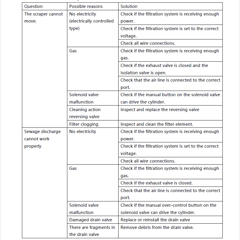

Warning:
Do not use this equipment beyond its design pressure. Doing so may cause equipment damage and safety accidents, for which our company will not be held liable.
This section provides comprehensive documentation for all products in the Pneumatic Self Cleaning Filter category. Please select a specific product below to view its detailed manual.
Available Products
SS304-350-Pneumatic Self Cleaning Filter-Duplex
Pneumatic Self Cleaning Filter
SS316-400-Pneumatic Self-cleaning filter
SS304-350-Pneumatic Self Cleaning Filter
SS316-273-Pneumatic Self Cleaning Filter
SS304-219-Pneumatic Self Cleaning Filter
SS304-273-Pneumatic Self Cleaning Filter
SS304-325-Pneumatic Self Cleaning Filter-SS304
Need Help?
If you need additional assistance with any product in this category, please contact our support team.