Sand Separator Manual
Table of Contents
Manual Overview
JX-GSF Sand Water Separator Installation and Operation Manual
1. Product Introduction
1.1 Preface
Before installing this equipment, please read this manual carefully to avoid unnecessary damage to the equipment.
The JX-GSF Sand Water Separator is typically designed and manufactured based on the design parameters provided by the user. Any modifications to the equipment must be approved by our company to prevent damage. Our company is not responsible for equipment malfunctions caused by non-quality-related reasons, but we can provide technical services.
1.2 Product Description
The JXGSF Sand Water Separator is used in the grit chambers of sewage treatment plants (stations). It is a sand-water separation device in sewage treatment, capable of separating particles ≥0.2mm with high separation efficiency, making it an ideal sand-water separation device.
Features:
- The sedimentation device and sand conveying device of the Sand Water Separator are of a closed integrated structure, featuring compact design, light weight, high operational reliability, and minimal maintenance requirements.
- The separation efficiency of the Sand Water Separator can reach 96%–98%, capable of separating particles ≥0.2mm with a recovery rate of no less than 98%.
- The shell, U-shaped trough, and other important components are made of stainless steel. The conveying screw in the U-shaped trough is a shaftless screw, designed to ensure smooth material flow without clogging. The shaftless screw body has sufficient strength and rigidity to ensure it does not deform or elongate under maximum working loads.
- The U-shaped screw trough is equipped with a sufficient number of replaceable liners, featuring a simple structure, long service life, and easy replacement.
- The equipment has no adjustable moving parts, resulting in low wear.
1.3 Working Principle and Performance
The sand-water mixture enters the equipment through the inlet pipe. Heavier particles such as sand settle at the bottom of the trough. Under the propulsion of the screw, the sand particles are lifted along the inclined U-shaped trough. After leaving the liquid surface, they enter the dewatering zone, where the sand particles continue to move upward while the water attached to them flows back to the water tank under gravity. The sand particles reach the sand outlet and fall into the sand collection bucket, while the separated water overflows from the weir and is discharged into the plant's sewage system.
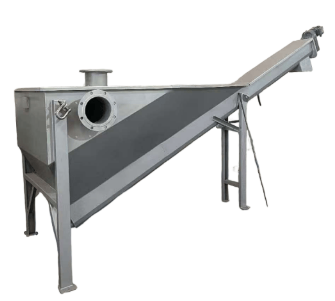
1.4 Main Structure
The Sand Water Separator mainly consists of a drive unit, screw body, water tank, and U-shaped trough.
1.4.1 Drive Unit
The drive unit uses a shaft-mounted reducer directly connected to the screw shaft. The drive unit employs a well-known brand motor suitable for outdoor use.
1.4.2 Screw Body
The screw body is a shaftless screw made of manganese steel, featuring high strength, good wear resistance, and ensuring smooth material flow without clogging.
1.4.3 Screw Sand Conveying Trough
The screw sand conveying trough has a U-shaped cross-section, installed at an angle of approximately 25 degrees. Except for the open discharge port, the rest of the structure is sealed with a flat cover and is detachable. The trough is made of stainless steel, and the interior is lined with nylon liners to prevent direct friction between the screw body and the trough. The nylon liners are detachable for easy replacement.
1.4.4 Water Tank
The water tank and the screw sand conveying trough form an integrated structure, made of stainless steel. It has sufficient strength and rigidity with no leakage. The entire structure is supported by steel beams fixed to the foundation.
2. Installation and Commissioning
2.1 Pre-Installation Preparation
- Familiarize yourself with the structure, function, and features of the equipment as shown in the installation diagram, and understand the relevant technical requirements.
- The loading and unloading of the equipment should be handled by designated personnel. After unloading, check the completeness of the equipment components against the delivery list and installation diagram. If necessary, perform maintenance, cleaning, and oiling, then arrange them neatly and cover them with oilcloth or plastic sheeting.
2.2 Installation
Attach the lifting lugs to the lifting hooks and lift the entire machine. Move the equipment horizontally to the accurate docking position, ensure the equipment is level, and connect the inlet and outlet water positions with flanges to ensure sealing.
Before starting the machine, conduct a comprehensive inspection and oiling of the equipment. Check that all fasteners are not loose; inspect the oil level in the reducer and add lubricating oil if necessary. For specific oiling methods and oil brands, refer to the "Gear Reducer Operation Manual."
2.3 Trial Operation
Start the motor momentarily to check if the shaftless screw rotates in the specified direction. The equipment must not reverse. Only after confirming no abnormalities, introduce the sand-water mixture through the inlet for trial operation.
2.4 Precautions
- The shaftless screw must rotate in the specified direction and must not reverse.
- Do not operate with the cover open to prevent debris from falling into the water tank and causing unexpected damage to the screw. Always disconnect the control cabinet power before opening the cover for maintenance or inspection.
- Do not apply force directly to the screw during handling or lifting. Use measures such as a support beam (pipe) to transmit force to avoid bending or elongation of the screw.
- Do not run the equipment empty for extended periods before water enters the tank to prevent dry friction between the screw's outer surface and the liners.
- After starting the machine, operators must check for any hard debris in the material. If any abnormality is detected, stop the machine immediately, troubleshoot, and resume operation only after resolving the issue.
3. Daily Maintenance and Care
3.1 Operational Maintenance
- When stopping the machine, stop the water inflow first. Wait until no sand is discharged from the sand outlet before stopping the machine to reduce the starting torque during the next startup.
- Regularly inspect the equipment during operation. If abnormal noise occurs, stop the machine immediately, troubleshoot, and resume operation only after resolving the issue.
- Regularly check the wear of the liners (monthly). Replace the liners if the wear exceeds 5mm. Do not allow the screw to directly contact the bottom of the U-shaped trough.
- Regularly check (monthly) the axial elongation of the screw due to fatigue. If the safety gap between the screw tail and the water tank plate is less than 20mm, adjust and lock it using the nut at the end of the drive shaft. If the adjustment is insufficient, cut off the excess length of the screw tail to ensure the safety gap. To ensure smooth operation, the cut screw tail must be rounded as per the original shape.
3.2 Lubrication Maintenance
Strictly follow the reducer operation manual to add the specified lubricant and replace it according to the prescribed run-in period and normal operation period.
The rolling bearings supporting the screw shaft neck should be lubricated with synthetic calcium-based grease (ZBE36005-88) every six months.
3.3 Reducer Maintenance
Refer to the Gear Reducer Operation Manual for details.
This section provides comprehensive documentation for all products in the Sand Separator category. Please select a specific product below to view its detailed manual.
Available Products
260-SS316-Sand Water Separator
360-SS316-Sand Water Separator
360-SS304-Sand Water Separator
260-SS304-Sand Water Separator
Need Help?
If you need additional assistance with any product in this category, please contact our support team.