Horizontal Decanter Centrifuge Manual
Table of Contents
Manual Overview
Operation Manual of Horizontal Screw
Discharge Decanter Centrifuge
 Operation Manual of LW Series Horizontal Screw Discharge Decanter Centrifuge
Ⅰ. Working principle:
The purpose of separation is to separate the solid in the mixture, or to separate two immiscible mixtures with different specific gravity. In a container containing a mixture of light and heavy liquids and solid particles, under the effect of gravity, stratification will occur after standing for a period of time. The solid particles with the largest specific gravity will sink to the bottom of the container, and the light liquid will stay at the upper part, and heavy liquid stays between the two. When the mixture enters the centrifuge drum and rotates with the drum at high speed, due to the effect of centrifugal force field, the stratification process will be accelerated, and is several thousand times faster than the process under gravity (the separation factor is the multiple of gravity acceleration). The solid particles in the mixed liquid have a large specific gravity and are subjected to a larger centrifugal force, and consequently they rapidly settle to the inner wall of the drum, while the liquid is squeezed to the center of the drum. If there is light phase and heavy phase, the heavy phase is close to the wall of the drum, and the light phase is close to the center of the drum. The liquid phase overflow port and solid outlet are set in the two-phase separator, and the light phase liquid and heavy phase liquid outlet and solid outlet are set in the three-phase separation. The centrifuge is equipped with a feed inlet and a screw feeder to make the whole separation process continuous.
In the separation process, the material enters the centrifuge from the feed pipe, in the high-speed rotating drum, the solid is thrown to the drum wall, the liquid is squeezed to the center of the drum, and the solid settled on the drum wall is pushed to the slag outlet by the screw conveyor, and discharged out of the machine. The separated liquid is discharged out of the machine through the overflow hole at the large end of the drum. The differential is a device to ensure the stability of the differential speed. The dual frequency conversion speed control device sharing the bus makes the drum speed and the differential speed stepless adjustable, which can adapt to the change of flow and concentration and automatically adjust the differential speed, so as to ensure good and satisfied separation effect.
Working principle diagram of horizontal screw centrifuge
 Ⅱ. Structure:
2.1 Drum: a high-speed rotating drum creates a centrifugal force field, where the mixture is separated. According to the requirements of slag removal and separation, the drum is designed into two parts: the cone section and the column section. In order to meet the requirements of discharge, we have drums with various cone angles and length-diameter ratio.
2.2 Screw: in order to make the solid settled on the drum wall be continuously pushed to the slag outlet of the conical drum mouth, the centrifuge is equipped with a screw feeder, which rotates in the same direction with the drum at a differential speed of 2~30 rpm (adjusted according to the type of material).
2.3 Differential: In order to keep the differential speed between the screw and the drum stable, the centrifuge is equipped with a differential, and the calculation of the differential speed is as follows:
△n= (n- principal - n-auxiliary)/i
Where △n - - differential speed (r/min)
n principal - - principal pulley speed (drum speed) (r/min)
n auxiliary -- auxiliary pulley speed (differential end) (r/min)
i -- differential speed ratio
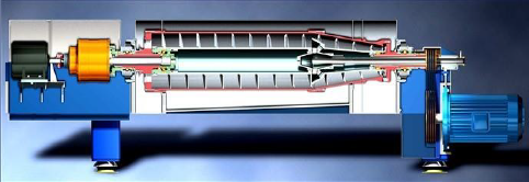
Structure diagram of horizontal screw centrifuge

Ⅲ. Technical conditions:
3.1 The height and size shall be determined by the user according to the arrangement of liquid outlet pipe and slag outlet.
3.2 The foundation can be made of concrete or steel structure, and the pipes shall be determined according to the installation requirements of liquid discharge pipe and slag discharge device. If the equipment is installed on the second floor, the floor slab shall be punched according to the foundation drawing to make the drain pipe and slag outlet pass through.
3.3 The level of foundation shall be calibrated: error ≤2/1000.
3.4 Since the machine is strictly calibrated for dynamic balance and equipped with shock absorbers, the machine should be seated on a qualified foundation platform and fixed with anchor bolts.
3.5 Ambient temperature: 0~50 ℃
3.6 Medium temperature 0~100 ℃
3.7 Installation site: indoor
Ⅳ. Instructions to users
4.1 Disassembly, cleaning, operation and maintenance of the centrifuge are not allowed before the operator understands the contents of this operation manual.
4.2 The centrifuge is not allowed to be operated before the machine is firmly installed.
4.3 Before operating the centrifuge, tighten the cover hold-down bolts.
4.4 In operation, if there is obvious abnormal noise and vibration, it should be stopped immediately.
4.5 Do not disassemble the centrifuge before the machine completely stops.
4.6 Disconnect the electrical switch and fuse when maintaining the centrifuge.
4.7 When cleaning the drum and screw feeder with cleaning solution, select those substances that do not corrode the drum and screw feeder materials.
4.8 When the centrifuge is not in use, disconnect the power supply of the main and auxiliary converters.
4.9 If welding and grinding is required for the maintenance of rotating parts such as drum and screw feeder, please contact us.
4.10 It is not allowed to disassemble the drum, and it is not allowed to change the position of the drum between each section of the drum or on other centrifuges.
4.11 The size of the tools used when disassembling the machine should be appropriate, please use the special tools delivered with the machine.
4.12 When the machine is not in use, ensure that the drum and screw do not contact with corrosive media. (Clean with clean water or detergent before shutdown)
4.13 When the machine is not in use, keep the equipment clean and turn the drum by hand at least once a week.
Ⅴ. Installation and use:
5.1 Installation
5.1.1 There should be room for operation and maintenance around the machine. There should be drum lifting equipment or space above the machine, the cone end feed pipe should have enough space for easy removal from the machine.
5.1.2 The foundation for centrifuge installation must be firm, flat and as horizontal as possible, and easy to operate and maintain.
5.1.3 When installing the machine, place the machine on the cement concrete or steel structure foundation to ensure stability.
5.1.4 Refer to the installation foundation drawing for installation dimensions.
5.2 Operation
5.2.1 Before start-up:
a. Check whether the feed pipe is connected correctly and whether the inlet and outlet valves are open.
b. Remove the sediment on the upper and lower covers.
c. Turn the safety seat at the end face of the gearbox by hand; make sure that you can easily turn the drum without friction and abnormal sound.
d. Check whether the overload protection switch and cover opening safety switch on the machine are normal.
e. Check whether the running direction of the main and auxiliary motors is consistent with the direction required.
f. Electrical installation shall be done by electricians to ensure accurate wiring and that it complies with relevant safety standards.
g. The belt should be tensioned: in the middle of the belt, apply a pressure of 20~30N/piece to the belt, and the belt deflection is 10~15mm.
5.2.2 Adjustment
a. Adjust the overflow device: the length of the settlement zone and the drying zone can be changed, thus affecting the separation effect: if the overflow plate radius R is large, the drying zone will be longer, and the settlement zone will be shorter. In the separation process, the solid phase is drier, but the solid content of separated liquid of the liquid phase will increase, which will affect the liquid output, and thus the optimum efficiency of the centrifuge will not be achieved. On the contrary, if the overflow plate radius R is small and the liquid effluent (separated liquid) of the liquid phase is good, but the liquid content of the solid phase will increase, and the separation fails. Therefore, size of the overflow plate directly affects the efficiency of the centrifuge, especially in the first use, it is required to determine the size of the overflow plate with the help of our technicians or professional commissioning personnel.
b. Adjust the differential speed: the differential speed is also an important parameter in the use of the centrifuge, and its size will also directly affect the efficiency of the centrifuge: the higher the differential speed is, the higher the liquid content in the solid phase is (the solid phase is not dry), which will affect the separation in the separation process; the lower the differential speed is, the higher the solid content in the liquid phase is.
During the initial commissioning of the equipment, the differential speed shall be determined according to the nature of the materials and the solid content of the feed, so as to achieve the optimum efficiency of the centrifuge.
In automatic control state, the differential speed is automatically adjusted according to the screw torque.
c. Adjust the feed volume: adjust the feed volume according to the liquid discharge and slag discharge to achieve the optimal separation effect.
d. When flocculant (such as sewage treatment) is needed, adjust the feed flow, which is also an important parameter that directly affects the separation.
During the initial commissioning, the feed liquid flow should be adjusted to the maximum and the material flow should be adjusted to the minimum, and then the material flow should be increased and the feed flow should be reduced according to the solid and liquid phase state.
Ⅵ. Lubrication
Lubricate the machine according to the lubrication diagram:
Lubrication diagram of horizontal screw machine

| No. | Grease | Oil adding interval | Oil quantity per time | Remarks |
| --- | ------ | ------------------- | --------------------- | ------- |
| 1 | Molybdenum disulfide lithium grease | Every 360 hours of operation | 20ml (fill 10 times with oil gun) | If there is no pulley, there is no such filler |
| 2 | L-CKD 220 # EP gear oil | Replace after the first operation for onemonth, and then every three months | 80% of gearbox | The oiling location is 2-10 o'clock at the oil filler |
| 3 | Molybdenum disulfide lithium grease | Before starting each shift | 10ml (fill 3-5 times with oil gun) | |
| 4 | Molybdenum disulfide lithium grease | Once a month | Fill oil to the outlet (9) 20ml | |
| 5 | Molybdenum disulfide lithium grease | Once a month | Fill oil to the outlet (10) 20ml | |
| 6 | Molybdenum disulfide lithium grease | Before starting each shift | 10ml (fill 3-5 times with oil gun) | |
| 7 | Molybdenum disulfide lithium grease | Every 360 hours of operation | 20ml (fill 10 times with oil gun) | If there is no pulley, there is no such filler |
| 8 | Oil outlet | Open the (2) (8) port at the same time when draining the oil, and seal one of them when addingoil | |
| 9 | Oil outlet | (4) Open this port when filling, and seal this port after filling | |
| 10 | Oil outlet | (5) Open this port when filling, and seal this port after filling | |
If the machine is equipped with thin oil lubritory, pay attention that:
1. The oil in the tank shall be recycled after being cooled by cooling water.
2. In thin oil lubrication, the oil is automatically circulated, and there is no No. 3 and No. 6 oil filler on the equipment.
3. When using the thin oil lubritory, pay attention to the steering of the oil pump, adjust the flow of the flowmeter (80-120L/h) and the pressure of the pressure gauge (0.4-0.5MPa).
4. The thin oil lubritory has to be filled with 46 # hydraulic oil, with a consumption of 60-70 liters.
Ⅶ. Maintenance:
7.1 The centrifuge must be maintained by trained and specialized persons.
7.2 The machine needs level I maintenance after running for 4000 hours and level II maintenance after running for 8000 hours. 8.2.1 Level I maintenance
1) Dismantle and wash the main bearing and bearing seat;
2) Clean the lubrication system;
7.2.2 Level II maintenance
1) Including Level I maintenance;
2) Disassemble and wash the differential;
3) Disassemble the main engine and clean the screw feeder bearing.
4) Dynamic balance of screw feeder
5) Complete machine installation and water filling dynamic balance of the machine
The specific maintenance interval shall also be determined according to the material conditions and working conditions.
Ⅷ. Disassembly and assembly of components
8.1 Remove planetary gear differential components
First, hang the differential with the belt conveyor head clamp, sling and hook, and the suspension height should be moderate, so as to avoid damaging the output shaft and bearing. Then remove the eight M16 socket head cap screws connecting the differential with the flange, and then screw two screws of the same specification into the ejection hole to eject the differential. In order to avoid breaking the dynamic balance, make an obvious mark at the corresponding position when disassembling.
In assembly, after aligning, use four screws to tighten diagonally, and then use an Allen wrench to tighten each bolt (please do make diagonal tightening).
 8.2 Disassembly diagram of large end bearing block

| No. | Name | Qty. | Remarks |
| --- | ---- | ---- | ------- |
| 1 | Differential | 1 | |
| 2 | Spline shaft | 1 | |
| 3 | Flange sleeve gland | 1 | |
| 4 | Flange sleeve | 1 | |
| 5 | Flat key | 1 | |
| 6 | Bearing pedestal gland | 2 | |
| 7 | O-ring | 2 | |
| 8 | Oil slinger | 2 | |
| 9 | Bearing housing | 1 | |
| 10 | Main bearing | 1 | |
| 11 | Frame oil seal | 1 | |
| 12 | Water retaining ring | 1 | |
| 13 | Outlet pressure plate | 4 | Part of types are not equipped with this item |
| 14 | Adjusting plate | 4 | Part of types have 6 or 8 adjusting plates |
| 15 | Large end cover shaft | 1 | |
| 16 | Frame oil seal | 2 | |
| 17 | Circlip | 1 | |
| 18 | Adjusting shim | 1 | |
| 19 | Spiral bearing | 1 | |
| 20 | Spiral bearing | 1 | |
| 21 | Circlip | 1 | |
| 22 | Frame oil seal | 2 | |
| 23 | Sealers | 1 | |
8.3 Disassembly diagram of small end bearing seat

| No. | Name | Qty. | Remarks |
| --- | ---- | ---- | ------- |
| 1 | Pulley gland | 1 | |
| 2 | Main pulley | 1 | |
| 3 | Flat key | 1 | |
| 4 | Bearing pedestal gland | 2 | |
| 5 | O-ring | 2 | |
| 6 | Oil slinger | 2 | |
| 7 | Bearing pedestal | 1 | |
| 8 | main bearing | 1 | |
| 9 | Retaining ring | 1 | |
| 10 | Small end cap shaft | 1 | |
| 11 | Frame oil seal | 2 | |
| 12 | Circlip | 1 | |
| 13 | Spiral bearing | 1 | |
| 14 | Adjusting shim | 2 | |
| 15 | Lubrication pad | 1 | |
| 16 | Frame oil seal | 2 | |
| 17 | Circlip | 1 | |
Ⅸ. Fault analysis and troubleshooting
| No. | Fault | Cause | Solution |
| --- | ----- | ----- | -------- |
| 1 | The machine cannotbe started | 1.No power supply2.The power supply issingle-phase or two-phase3.The motor is damaged4.The acceleration time of the frequency converter is set too short5.The frequency converter is damaged6.Drum and screw plugging | 1.Check the power supply2.Check the fuse wire3.Repair or replace the motor4. Reset the acceleration time5.Check or replace the frequency converter 6.Remove the accumulated material in the drum and screw |
| 2 | Large vibration during startup | 1.Material accumulation in drum and screw (not cleaned)2.Loose parts in the drum or screw parts3.Main bearing or screw support bearing is damaged4.The anchor bolts of the main machine or motor are loose5.Rigid connection between feed pipe and centrifuge6.During maintenance and assembly, the scoring line of the drum is misaligned or the screw is seriously damaged7.The drum rotating dynamicbalance is broken | 1.Rinse with clean water repeatedly, remove the differential pulley belt, fix the drum, and turn the differential pulley reversely to drain the residue2.Shut the machine down for maintenance3.Replace the bearing4.Tighten the loose bolts5.Make flexible connection according to the requirements of this manual6.Re-align the scale mark and repair the screw for dynamic balance correction7.Recalibrate the dynamic balance of the drum |
| 3 | The separated liquid phase is unclear | 1.The processing capacity is too large2.The overflow radius is too large3.The flocculant does not flocculate or the flocculation pipeline is blocked | 1.Reduce processing capacity2.Reduce overflow radius3.Do sample test again to check flocculation effect, and check feed pump and pipeline |
| 4 | No solid phasedischarge | 1. Overflow radius is too large 2. The differential speed is too small3. The concentration is too low or the feed volume is too small, and | 1. Reduce overflow radius2. Increase differential speed3. It is normal that no material is discharged within 10 minutes 4. Dredge the pipeline |
| | | the solid phase did not fill the gap between the drum and the screw 4. The feed pipe is blocked5.The main engine runs in the opposite direction6.The belt is too loose, and the drum and screw runsynchronously7.The differential is damaged8.The solid phase of the material is too fine or too sticky | 5.Turn and rotate as required6.Tighten the belt7.Repair the differential8.Increase the separation factor or increase the differential speed, or readjust the process parameters |
| 5 | Solid phase discharge is too wet | 1.The overflow radius is too small2.The differential speed is too large | 1.Increase overflow radius2.Reduce differential speed |
| 6 | The differential is hot and noisy | 1.Differential lubrication oil runs out 2.The bearings or parts ofdifferential are damaged | 1.Add lubricating oil2.Replace the damaged bearings or parts |
| 7 | Temperature of main bearing is too high | 1.Lubrication system failure2.Bearing damage3.Too much oil for bearing | 1.Check and remove the fault2.Replace the main bearing3.Stop adding grease for 1 to 2 days, and run the machine at low or medium speed for a period of time |
| 8 | The running current keeps rising | 1. Plugging2.The outlet is too thin | 1.Stop feeding, wash the machine with water, adjust feeding parameters andincrease differential speed2.Enlarge the liquid outlet pipe and dredge the pipe to reduce the liquid outlet back pressure |
Ⅹ. Energy saving of horizontal screw centrifuge
The special advantages of Kaida horizontal Screw Centrifuge: reduce the installed capacity of the motor and reduce power consumption.
The damping reduction that direct drives the gearbox screw is driven by a variable frequency motor, hence the energy consumption could be reduced. Consequently the whole system can save more than 10% energy, which is particularly important in an era that is troubled by energy shortage.

This section provides comprehensive documentation for all products in the Horizontal Decanter Centrifuge category. Please select a specific product below to view its detailed manual.
Available Products
SS2205-350+3P-Horizontal Decanter Centrifuge
SS316-350+3P-Horizontal Decanter Centrifuge
SS316-650+2P-Horizontal Decanter Centrifuge
SS2205-350+2P-Horizontal Decanter Centrifuge
SS316-350+2P-Horizontal Decanter Centrifuge
SS2205-550(2)-Horizontal Decanter Centrifuge
SS304-550(2)-Horizontal Decanter Centrifuge
SS304-250(2)-Horizontal Decanter Centrifuge
SS2205-450(2)-Horizontal Decanter Centrifuge
SS2205-450(3)-Horizontal Decanter Centrifuge
SS304-450(3)-Horizontal Decanter Centrifuge
SS316-250(2)-Horizontal Decanter Centrifuge
SS304-450(2)-Horizontal Decanter Centrifuge
SS316-450(3)-Horizontal Decanter Centrifuge
SS316-550+2P-Horizontal Decanter Centrifuge
SS2205-250+2P-Horizontal Decanter Centrifuge
SS316-550(3) Horizontal Decanter Centrifuge
SS304-350+3P-Horizontal Decanter Centrifuge
SS304-550+3P-Horizontal Decanter Centrifuge
SS304-900+2P-Horizontal Decanter Centrifuge
SS304-750+2P-Horizontal Decanter Centrifuge
SS304-650(2)-Horizontal Decanter Centrifuge
SS316-450(2)-Horizontal Decanter Centrifuge
SS304-350(2)-Horizontal Decanter Centrifuge
Need Help?
If you need additional assistance with any product in this category, please contact our support team.