Basket Filter Manual
Table of Contents
Manual Overview
Double/Triple Basket Filter
Control Panel
Operation Instructions
I. Overview
This control panel is specifically designed for duplex basket filter equipment. In today's era of widespread automatic filter application, we enhance product competitiveness by reducing costs and improving product performance for filters.
Developed under the guidance of industry experts, this control panel fully considers the various operating conditions and related control procedures of duplex basket filter equipment. Serving as the electrical control core of the filter equipment, it features multiple protection and alarm functions. It offers both automatic and manual control modes, with performance exceeding similar foreign products.
This control panel possesses automatic and manual functions. In automatic mode, it operates according to the program set in the PLC. In manual mode, electric valves can be individually opened/stopped, offering simple and clear operation. This control panel is the essential and optimal control core for the filter.
The control panel utilizes imported components, including the latest version Siemens PLC, Siemens 10-inch touch screen, Schneider low-voltage electrical devices, and a stainless steel enclosure.
II. Operation and Application
2.1 Main Interface
2.1.1 Double basket filter

- Panel Electric Valve A, B Status: Red indicates working, Green indicates stopped.
- Panel Displays: Filter A/B inlet pressure, outlet pressure, and differential pressure value.
- Current Mode: Displays Manual or Automatic mode.
- Current Status: Displays status for Filter A/B Working, Filter A/B Switching, Filter A/B Alarm, Filter A/B Cleaning.
- Differential Pressure Delay Switching Time: Displays the current delay time for filter switching based on differential pressure.
- Valve Fully Open Delay Closing Time: Displays the current delay time for closing the valve after it is fully open.
- External Inputs: Displays Emergency Stop status, Filter A/B Valve Alarm.
- Mode Selection: Options for Manual and Automatic mode selection.
- In Manual mode, the interface displays four manual buttons: Open Valve A, Close Valve A, Open Valve B, Close Valve B.
- In Automatic mode, the manual buttons are hidden.
- Parameter Setting: Used to enter the parameter setting interface.
- Differential Pressure Setting: Used to enter the differential pressure setting interface.
- Alarm Reset: Press this button to manually silence the alarm sound when a fault alarm occurs.
- Cleaning Completed: After manually cleaning the faulty filter, press this button to switch to the non-faulty filter for operation.
2.1.2 Triple basket filter
 Status of Panel Electric Valves A, B, C: Red indicates operating, Green indicates stopped.
- Panel Displays: Filter A/B inlet pressure, outlet pressure, and differential pressure value.
- Current Mode: Displays Manual or Automatic mode.
- Current Status: Displays status for Filters A, B, C: Working, Switching, Alarm, Cleaning.
- Differential Pressure Delayed Switching Time: Displays the current setting for the filter switch delay after differential pressure is reached.
- Valve Open Position Delayed Closing Time: Displays the current delay time after valve fully opens before closing command.
- External Inputs: Displays Emergency Stop status, Valve Alarm status for Filters A, B, C.
- Mode Selection: Options for Manual and Automatic mode.
- Manual Mode: Interface shows six manual buttons: Open Valve A, Close Valve A, Open Valve B, Close Valve B, Open Valve C, Close Valve C.
- Automatic Mode: Manual buttons are hidden.
- Parameter Setting: Button to access the Parameter Setting interface.
- Differential Pressure Setting: Button to access the Differential Pressure Setting interface.
- Alarm Reset: Press this button to manually silence the audible alarm when a fault alarm occurs.
- Cleaning Complete: After manually cleaning the faulty filter, press this button to switch to a non-faulty filter for operation.
2.2 Parameter Setting Interface

- Differential Pressure Delay Switching Time setting. Factory setting: 5 seconds (Modification not recommended)
- Valve Fully Open Delay Closing Time setting. Factory setting: 5 seconds (Modification not recommended)]
2.3 Differential Pressure Setting Interface
2.3.1 Double basket filter

- Differential Pressure Range: Used to set the pressure transmitter range.
- A/B Switching Differential Pressure: Used to set the differential pressure value for A/B switching. [Factory setting: 0.15 bar (Can be modified according to actual conditions, range generally controlled between 0.1~0.8 bar)]{.mark}
- A Inlet Pressure: Displays Filter A inlet pressure value.
- A Outlet Pressure: Displays Filter A outlet pressure value.
- A Differential Pressure: Displays Filter A differential pressure value.
- B Inlet Pressure: Displays Filter B inlet pressure value.
- B Outlet Pressure: Displays Filter B outlet pressure value.
- B Differential Pressure: Displays Filter B differential pressure value.
2.3.2 Triple basket filter
 A Inlet Pressure: Displays the inlet pressure value for Filter A.
- A Outlet Pressure: Displays the outlet pressure value for Filter A.
- B Inlet Pressure: Displays the inlet pressure value for Filter B.
- B Outlet Pressure: Displays the outlet pressure value for Filter B.
- C Inlet Pressure: Displays the inlet pressure value for Filter C.
- C Outlet Pressure: Displays the outlet pressure value for Filter C.
- Differential Pressure Range: Sets the range for the pressure transmitters.
- A/B/C Switching Differential Pressure: Sets the differential pressure value at which A/B/C filter switches. [Factory setting: 0.15 bar (can be modified based on actual conditions, range generally controlled between 0.1 ~ 0.8 bar)]
- A Differential Pressure: Displays the calculated differential pressure value for Filter A.
- B Differential Pressure: Displays the calculated differential pressure value for Filter B.
- C Differential Pressure: Displays the calculated differential pressure value for Filter C.
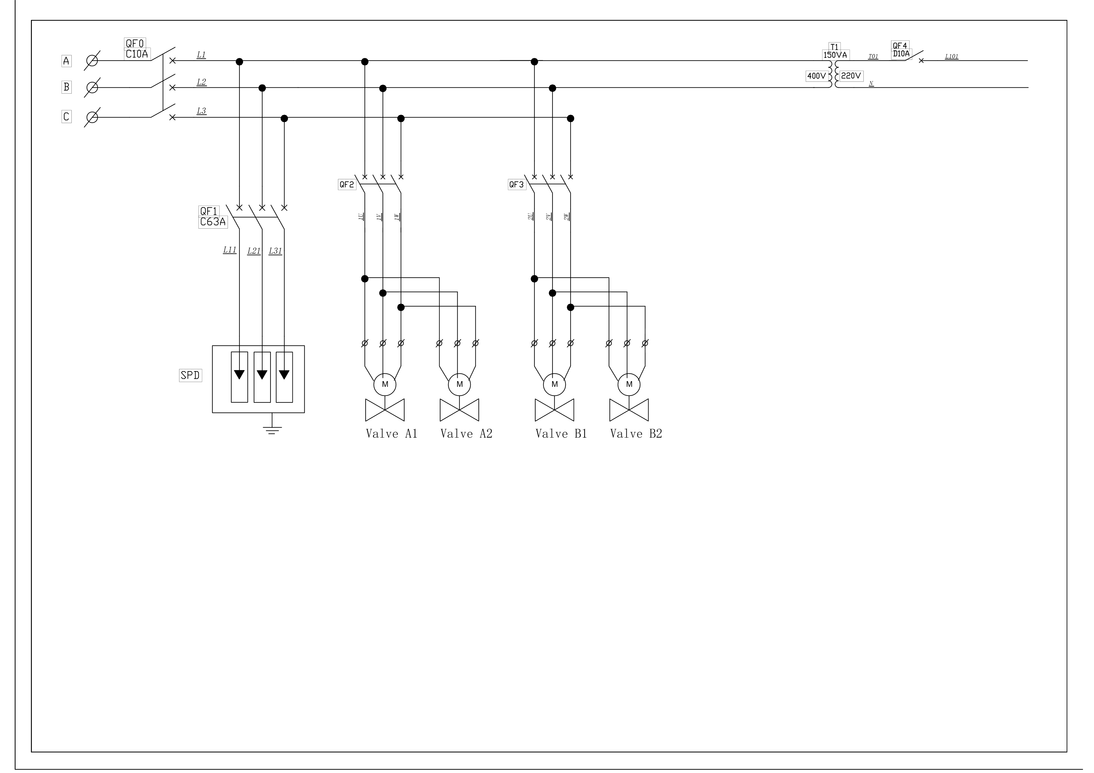
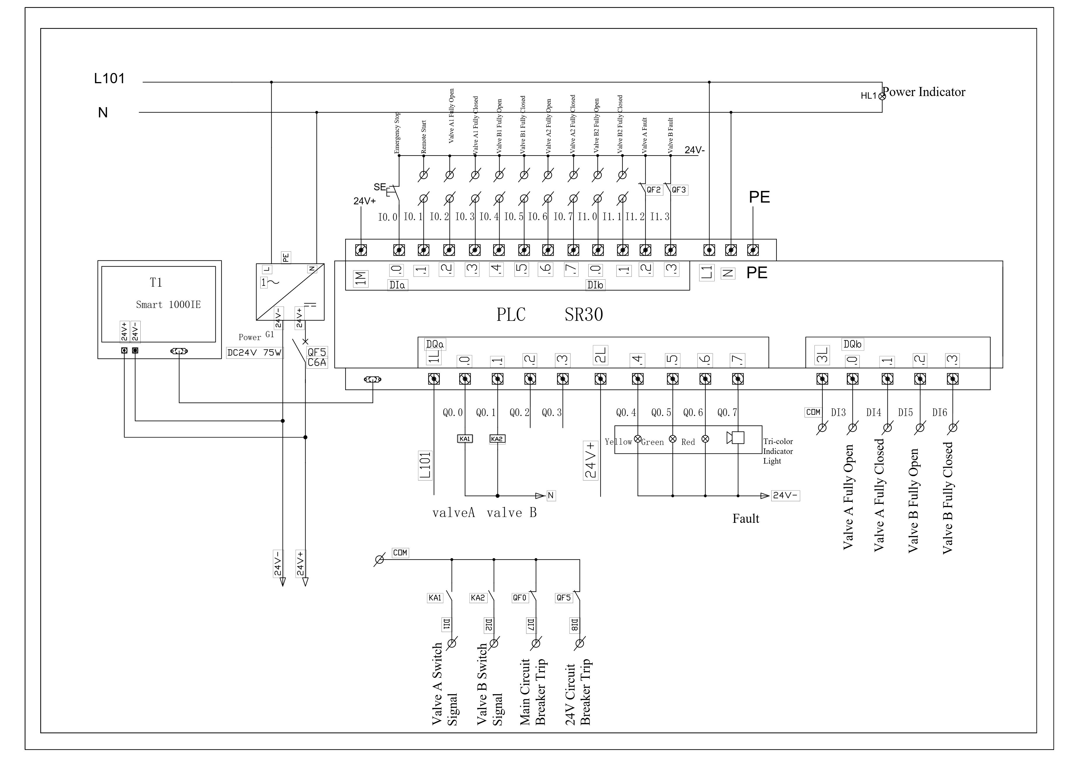
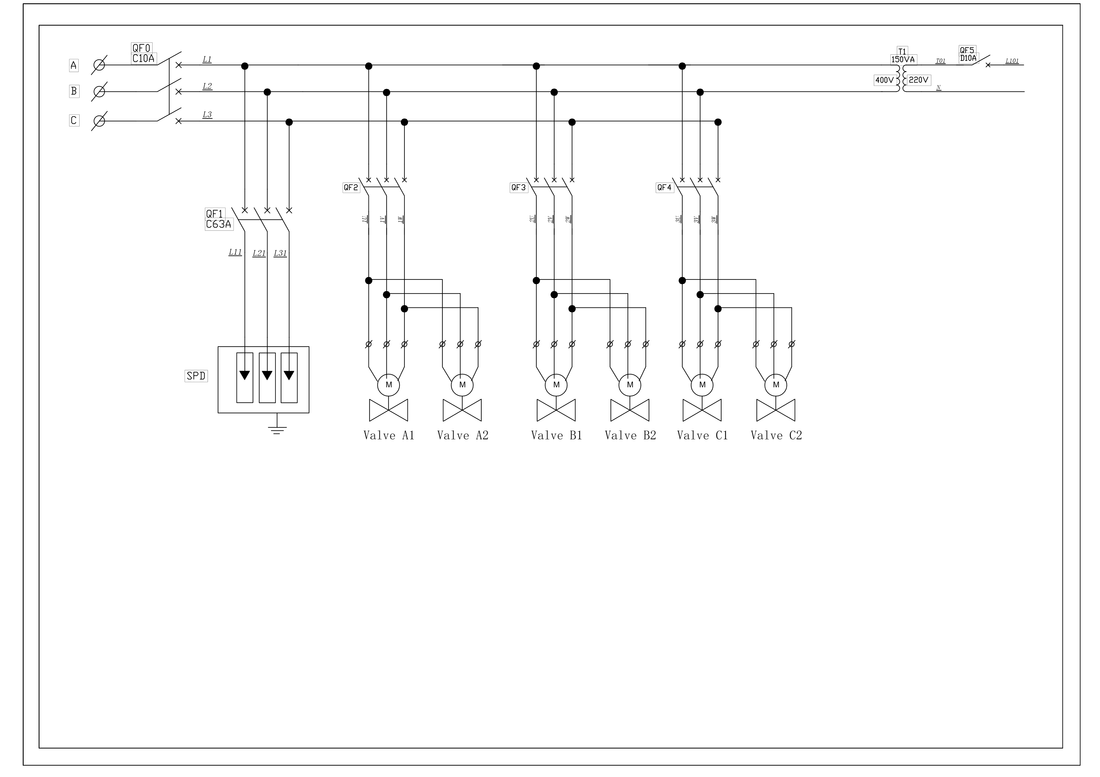
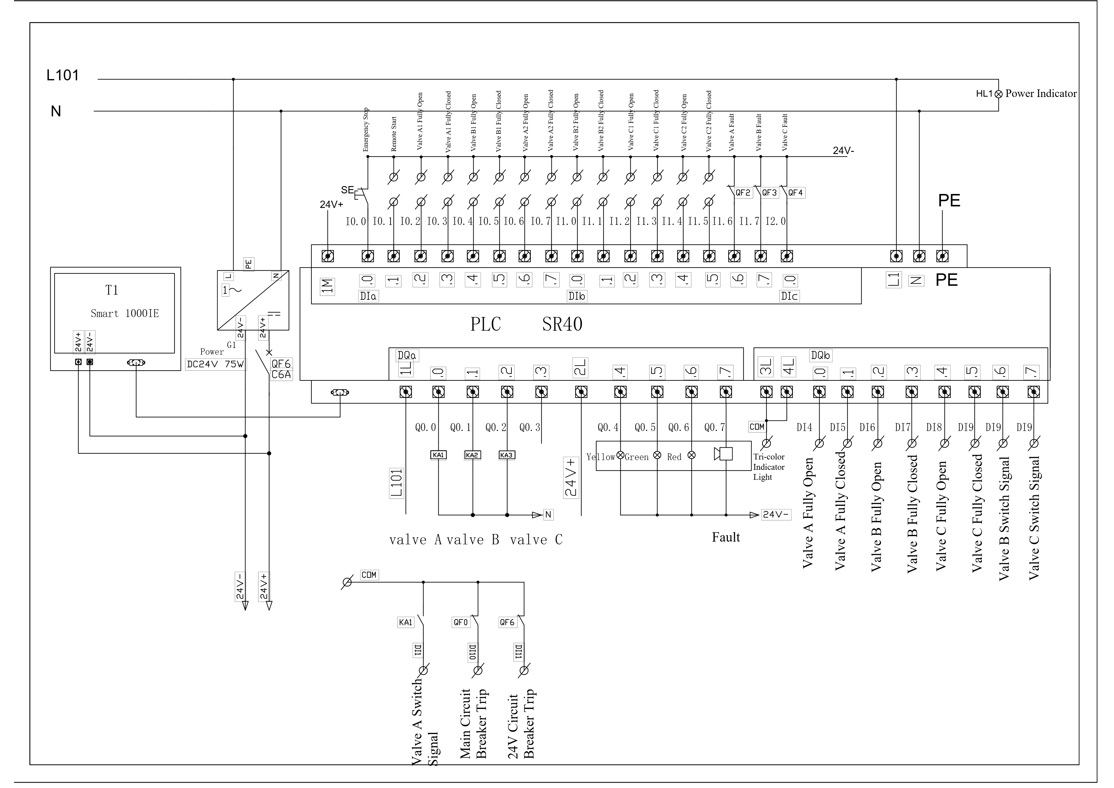
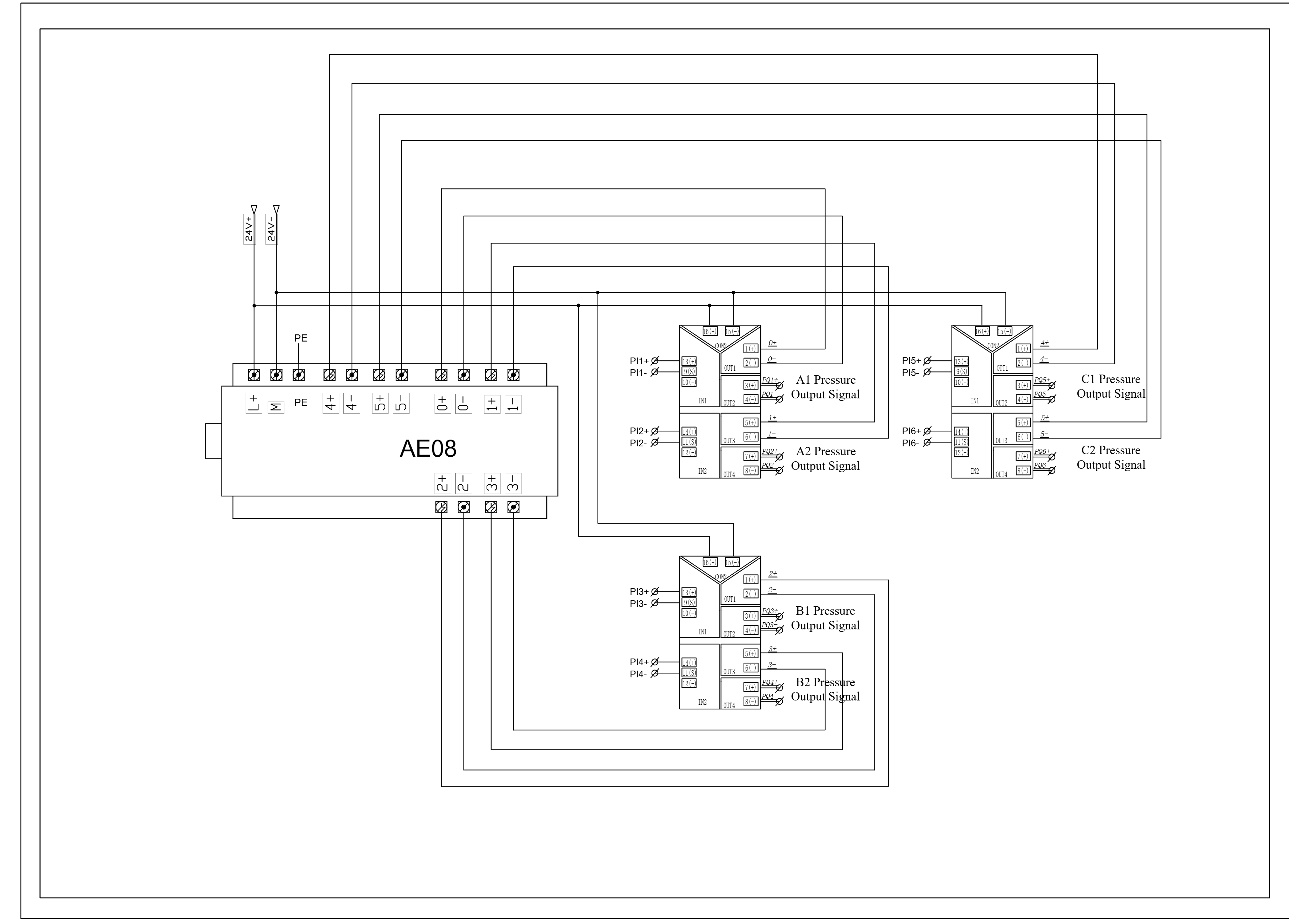
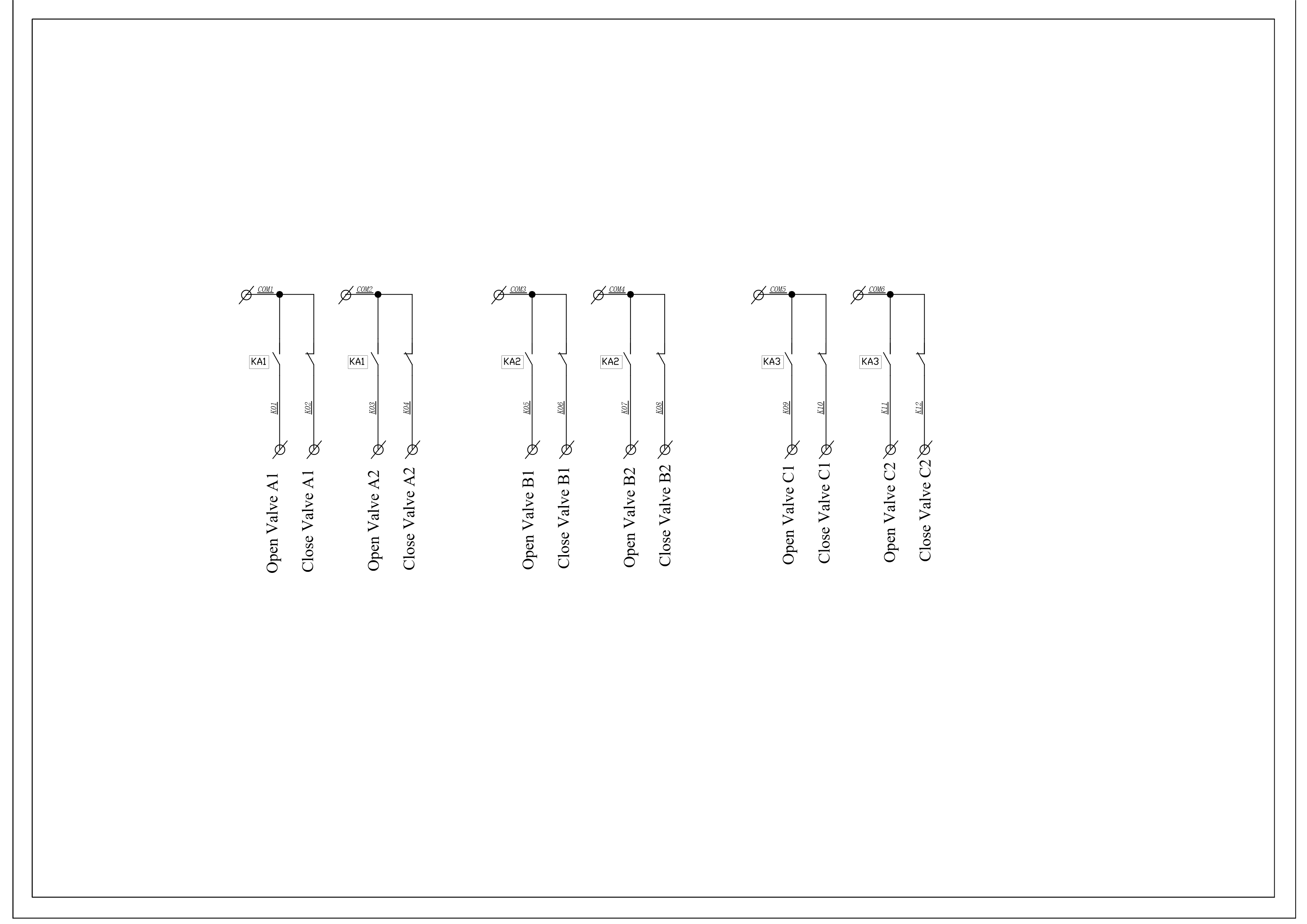
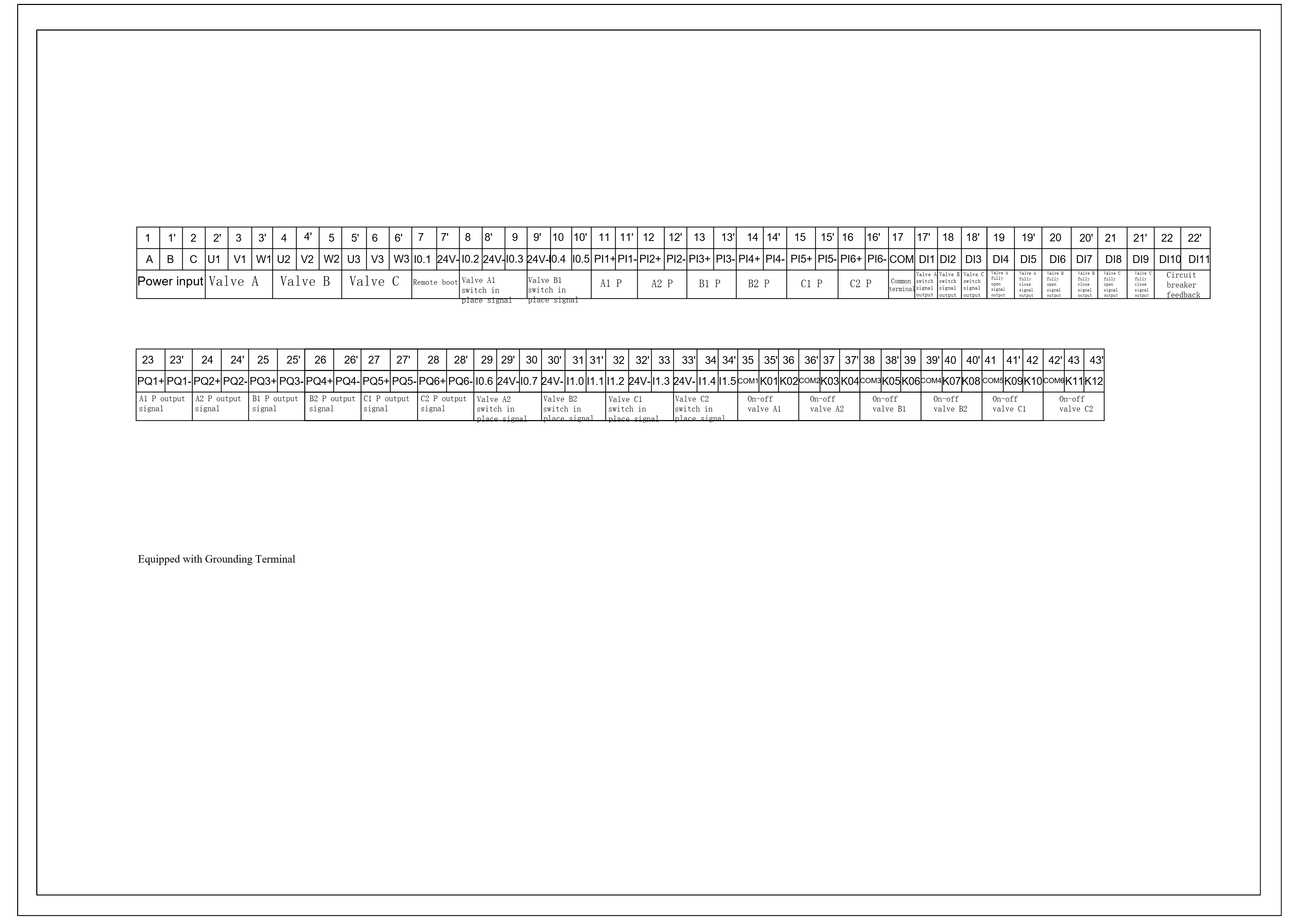
2.4 Circuit Diagram
Please refer to Attachments: Drawings.
An external three-color alarm light is configured on the enclosure:
- Green Light: Indicates either Filter A or B is working.
- Yellow Light: Indicates the working filter has a fault and is switching to the other filter.
- Red Light + Alarm Sound: Indicates one filter has a fault requiring manual cleaning.
- Red Light Only: Indicates manual cleaning of the faulty filter is in progress.
2.5 The wiring diagram for the intelligent switch-type electric actuator

For the debugging method of the maximum open limit (HH) and maximum close limit (LL) of the intelligent switch-type electric actuator, please refer to the separate video. No phase sequence required!
III. Quick-Open Basket Filter Mechanical Operation and Maintenance Manual
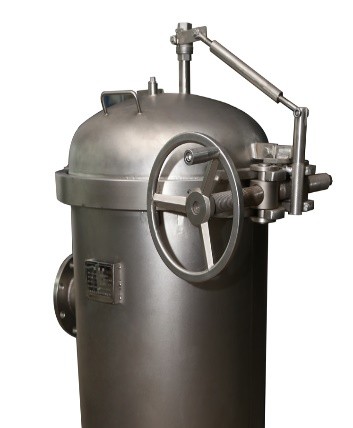
3.1 Overview of Quick-Open Mechanism
The quick-open filter, due to its reasonable structure, meticulous manufacturing, and strict quality control, ensures safe and reliable use. However, improper installation and operation may still cause damage to the filter.
Operators must correctly assess the potential environmental impact of filter failure and implement corresponding preventive measures to ensure safe operation of this product.
The filter must be used correctly and safely. Adhere to labor safety protection and accident prevention regulations, especially those concerning technical working media (GSG) and pressure vessel regulations. General safety, usage, and maintenance regulations or requirements are detailed on subsequent pages.
DANGER: NEVER open the filter top cover before the filter inlet/outlet valves are closed AND the drain valve is vented!
The quick-open multi-bag filter allows lid opening/closing operations to be completed in less than 30 seconds. This eases operator workload while reducing downtime, maintenance costs, and delivering practical economic benefits.
3.2 Filter Commissioning
Refer to the following steps before installing the filter basket and starting operation:
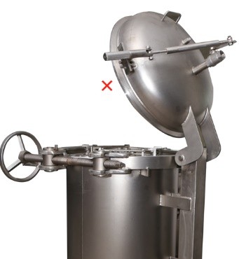
- Lift the safety lock handle and rotate the lid locking wheel counterclockwise.
- Once all lid clamps are fully released, lift the lid handle to swing the top cover upwards. When replacing the basket, swing the cover to its maximum position.
- Place the filter basket into the filter housing. The seal ring must be checked for damage and correct seating.
- Ensure the basket neck sits flat. Place the compression ring (clamping ring) on top. The compression ring can be easily rotated and locked using a special tool. The handle on the compression ring MUST be rotated into the positioning notch; otherwise, there is a risk of the ring loosening.
- Before lowering the top cover, inspect the sealing surfaces and seal ring for [damage and cleanliness. Keeping the V-flange and clamp locking device clean is crucial]. Replace damaged seal rings promptly! Ensure the seal ring is correctly positioned.
- The procedure for locking the compression ring is the reverse of opening.
- After installing the basket, swing the lid back down, rotate the lid locking wheel clockwise, and pull down the safety lock handle to lock it. The filter is now ready for use.
- Slowly open the inlet pipe valve. Caution: Do not open too quickly to prevent sudden pressure surges from rupturing the basket or damaging other components. Ensure the vent valve is open to purge air from the filter. Close the vent valve immediately once liquid flows out. Operators must take safety precautions when filtering hazardous liquids to avoid contact (often connect a bent tube to the vent valve for drainage).
- If residual air remains trapped inside the filter, it may affect filtration efficiency; therefore, vent periodically.
- Now slowly open the outlet valve (to put into operation).
3.3 Filter Maintenance
Normally, the filter requires no special maintenance. However, for equipment equipped with the quick-opening clamp, proper maintenance of the seal system is crucial for long-term leak-free operation. After each lid opening, the sealing surfaces and O-ring groove MUST be thoroughly cleaned using pressurized water jets before re-closing the lid. This prevents foreign particles (e.g., solid debris, plant fibers, powder) from remaining in the sealing area, which could compromise seal integrity and cause leaks during operation. All components should be regularly inspected for corrosion and other damage. Basket replacement depends on clogging status and changes in the filtered medium. Clogging is determined by the pressure differential across the filter inlet/outlet.
- Pump Suction (Pre-filter) Use: We recommend replacement at a differential pressure of 0.15 bar (maximum up to 1.2 bar). Otherwise, there is a risk of basket rupture. Before replacing the basket, the vent valve MUST be opened to depressurize the filter. The remaining operational steps are identical to Section 3.2 "Commissioning".
Declaration: Although seal rings are often reused in practice, our company supports the seal ring supplier's recommendation that the seal ring should be replaced every time the filter is opened. Seal ring failure does not indicate a defect in the filter.
3.4 Lid Locking Mechanism Maintenance
- The lid balancer should operate precisely and be adjustable, allowing the lid to stay in any position. Adjust the tightness of the bolt below the balancer so the lid stays in any position.
Safety Precautions:
- The lid balancer must not contact corrosive substances.
- Although the lid can stay in any position, do not leave it in a half-open state.
- When replacing the basket, open the lid to its maximum safe position.
- If lid removal is necessary, the lid must be opened to its maximum safe position.
- WHEN OPENING THE LID TO REPLACE/CLEAN THE BASKET, THE INLET AND OUTLET MANUAL KNIFE GATE VALVES OF THE FILTER MUST BE CLOSED. THIS IS VERY IMPORTANT FOR SAFE OPERATION!!!
Attachment 1: Drawings-Double basket filter
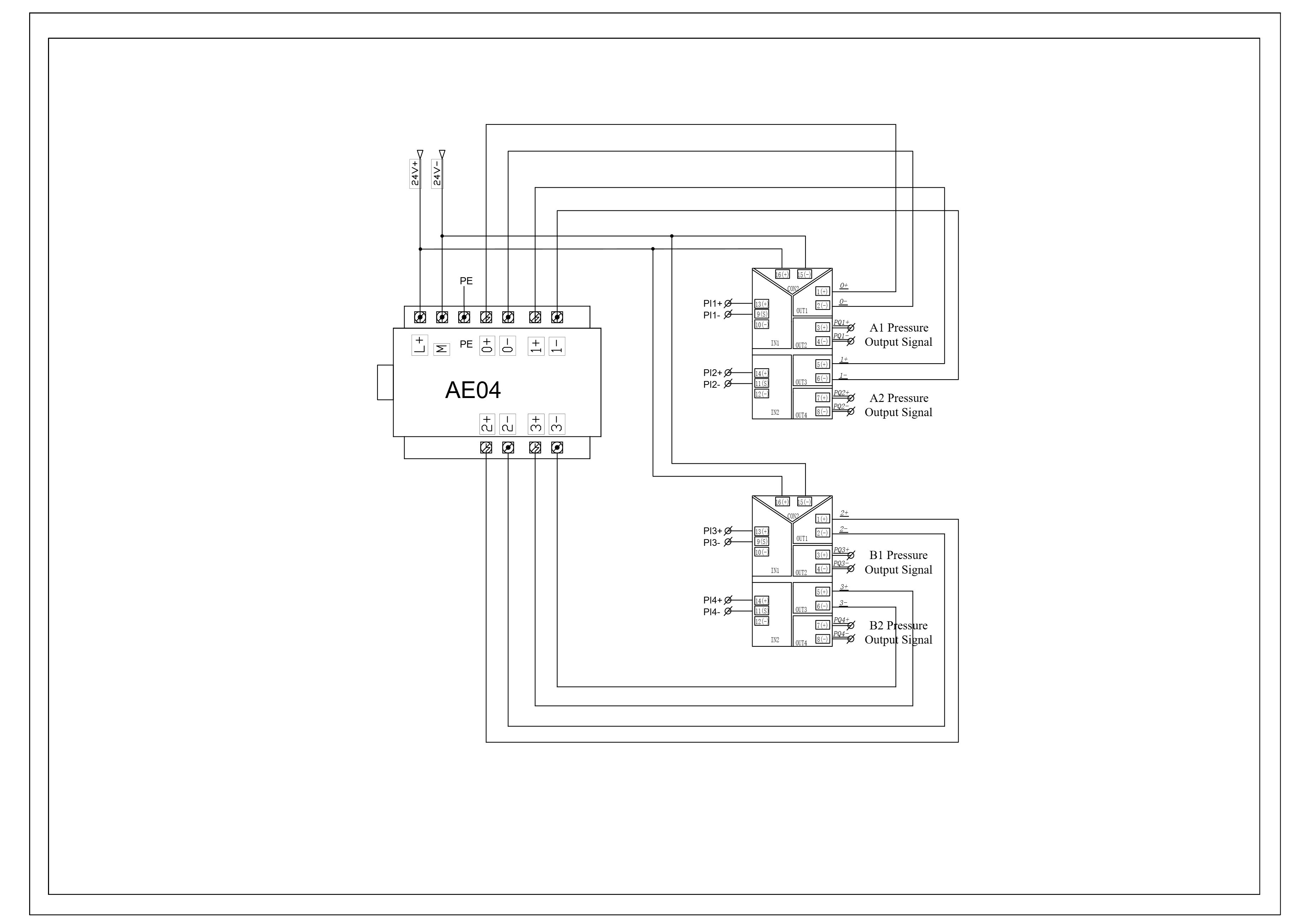
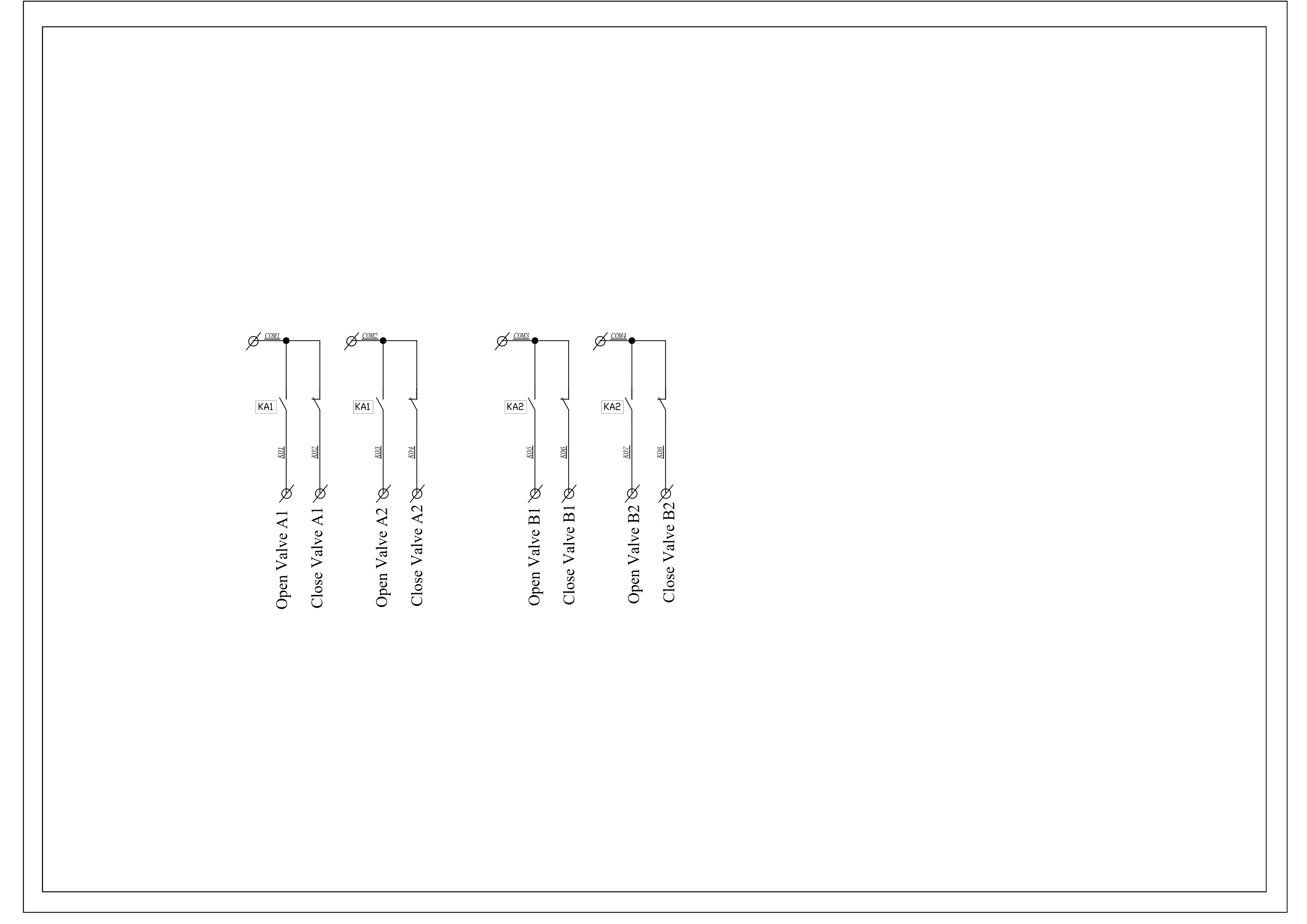
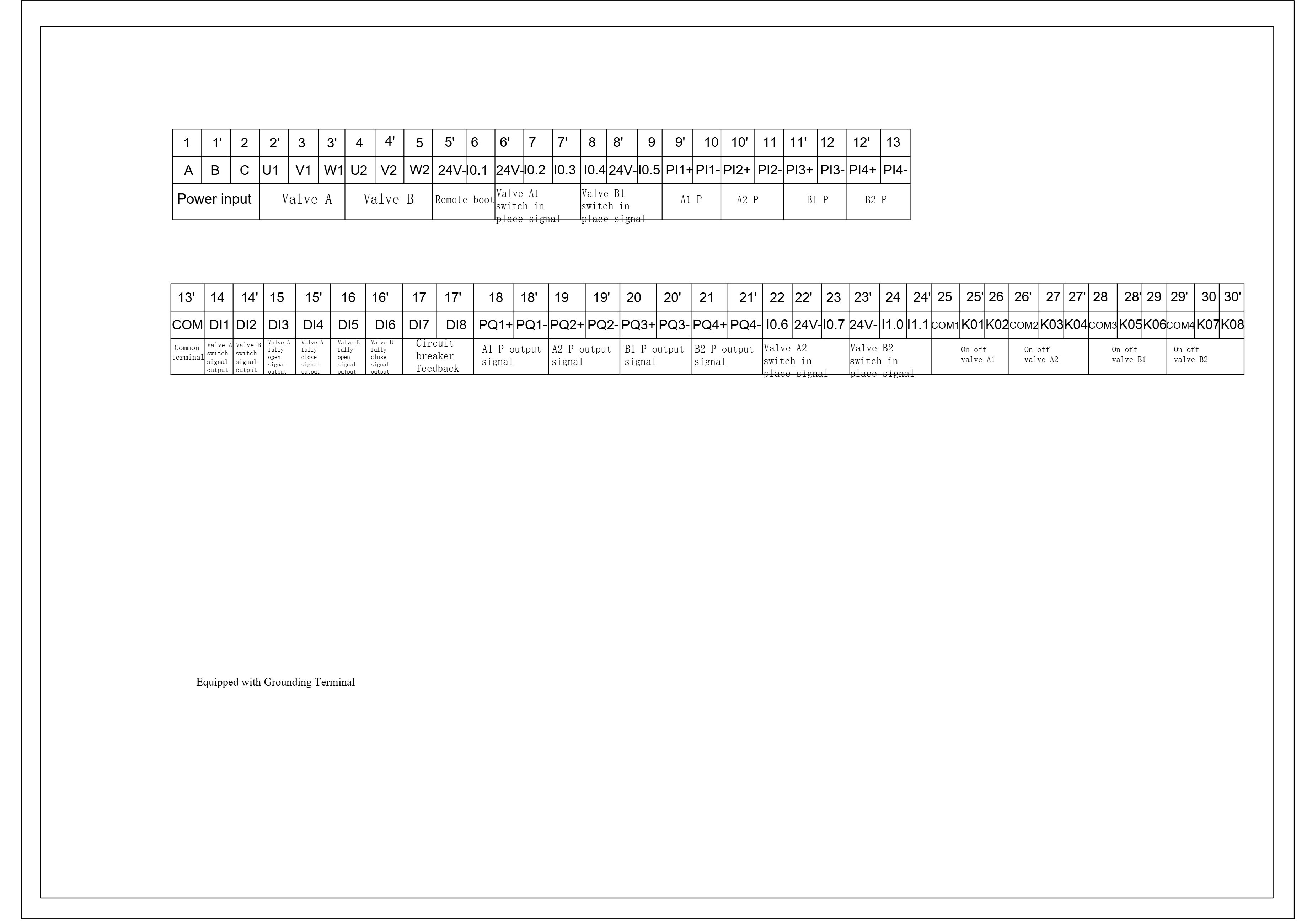
Attachment 2: Drawings-Triple basket filter
This section provides comprehensive documentation for all products in the Basket Filter category. Please select a specific product below to view its detailed manual.
Available Products
8"(325)-SS316-Basket Filter
8"(325)-SS304-Basket Filter
114-SS304-Basket Filter
12"(600)-SS304-Dual-Basket Filter
12"-SS316-Basket Filter
12"-SS304-Basket Filter
10"-SS316-Basket Filter
10"-SS304-Basket Filter
8"-SS316-Basket Filter
8"-SS304-Basket Filter
6"-SS316-Basket Filter
6"-SS304-Basket Filter
5"-SS316-Basket Filter
5"-SS304-Basket Filter
4"-SS316-Basket Filter
4"-SS304-Basket Filter
3"-SS316-Basket Filter
3"-SS304-Basket Filter
2"-SS316-Basket Filter
2"-SS304-Basket Filter
SS304-8"-Duplex Basket Filter
SS304-6"-Basket Filter
Basket Filter
SS304-8"-Basket Filter
SS304-3"-Duplex Basket Filter
SS304-12"-Φ326-Basket Filter
Need Help?
If you need additional assistance with any product in this category, please contact our support team.