Externally Fed Rotary Drum Screen Manual
Table of Contents
Manual Overview
INSTALLATION INSTRUCTIONS
For
WLW ROTARY DRUM FILTER
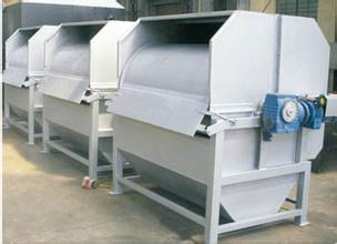
I. Product Introduction
1. Foreword
Please read this manual carefully before installation to avoid unnecessary damage to the equipment.
WLW rotary drum filter is widely used in the filtration of various occasions where solid-liquid separation is required such as urban domestic sewage, fruit plants, papermaking, textiles, printing and dyeing and chemical wastewater etc.
WLW rotary drum filters are usually designed and manufactured based on user s’ design parameters. If the equipment needs being modified, it must be approved by our company so as not to damage the equipment. The company will not be responsible for equipment failures caused by non quality reasons, but our company can provide technical services.
2. Supplying scope
The rotary drum filter provided by the company for this project is a complete set of equipment, which includes:
Drive device, main shaft, rotary filter screen, spray device <cleaning filter screens>, water buffering and distribution baffle, removable sealing plate, water inlet, water outlet, vent valve, scraper and other components.
3. Briefings and Working Principle
The AC speed regulating motor drives the screen cylinder through a speed reducer and the sewage passes through the inlet to the tank and rises to the filtered water line through the water buffering and distribution baffle. The purified water enters the cylinder body through the gap of the screen and is discharged outward at the bottom of the screen cylinder, and the screen is cleaned at the same time. The impurities and fiber like organic matters that are larger than the screen gap are blocked by the screen and adhered to the surface of the drum, and are carried by the rotating drum to the other side, and finally discharged by the unloader. The filtered sewage flows to the outlet tank and drains through the outlet.
II. Installation and Debugging
1. Preparations
First, familiarize yourself with the structure, function and characteristics in the installation diagram and understand the relevant technical requirements of the equipment;
Special personnel shall be responsible for the loading and unloading of the equipment. After the unloading, the equipment parts shall be inspected according to the delivery list and the equipment installation drawing for completeness and damages.
If necessary, carry out maintenance, cleaning and oiling, then put them neatly and cover them with tarpaulin or plastic cloth.
2. Installation
Put the lifting lug above the device into the lifting hook and lift the whole machine, place it in a positive position to ensure the horizontality of the main shaft and the whole machine should be on a horizontal plane, slowly move it to the designated place. The water inlet and outlet shall be tight coupled with corresponding pipes through flanges and rubber pads. Tight couple the water inlet and the equipment.
Connect the vent valve to the raw water tank, the vent valve is used for cleaning the equipment. Carefully check that all parts of the equipment are firmly connected without looseness.
3. Commissioning
Comprehensive inspection and oiling is needed before starting to ensure fasteners are fastened and the oil level in speed regulator gearbox is at the right place.
Check the Instant Start motor to ensure its screen cylinder is rotating in the right direction before starting.
Start trial run after no load operation for 2 to 3 hours without any abnormalities (This equipment has been tested for 8 hours without any abnormalities before delivery).
III. Daily Maintenance
In the course of operation, in case of fiber impurities twining around the main shaft, it should be stopped and cleaned manually in order to avoid affecting the normal operation and increasing the load of the reducer
Adjust the reducer speed according to dregginess in the water so as to reach the maximum efficiency.
Apply lubricating grease (2# calcium grease) once a week for P-type rolling bearings, and inject it with a grease gun in the nozzle
IV. Common Faults
This equipment is stable in operation. It can work smoothly for long hours under regular maintenance and proper rotating direction of the drum. Please feel free to contact our Technical Department if you have any problems with troubleshooting.
This section provides comprehensive documentation for all products in the Externally Fed Rotary Drum Screen category. Please select a specific product below to view its detailed manual.
Available Products
SS304-1000*2000-Externally Fed Rotary Drum Screen
SS316-600*800-Externally Fed Rotary Drum Screen
SS316-800*1200-Externally Fed Rotary Drum Screen
SS316-800*1000-Externally Fed Rotary Drum Screen
SS316-500*500-Externally Fed Rotary Drum Screen
SS316-500*650-Externally Fed Rotary Drum Screen
SS304-500*650-Externally Fed Rotary Drum Screen
SS304-400*500-Externally Fed Rotary Drum Screen
SS316-400*500-Externally Fed Rotary Drum Screen
SS304-800*1000-Externally Fed Rotary Drum Screen
SS304-800*1200-Externally Fed Rotary Drum Screen
SS304-1000*3000-Externally Fed Rotary Drum Screen
SS304-500*600-Externally Fed Rotary Drum Screen
SS304-500*500-Externally Fed Rotary Drum Screen
SS316-500*600-Externally Fed Rotary Drum Screen
SS304-600*800-Externally Fed Rotary Drum Screen
Need Help?
If you need additional assistance with any product in this category, please contact our support team.