Sludge Dewatering Manual
Table of Contents
Manual Overview
I. Safety Precautions
◆Alarms and Main Signs
For nip in the bud, this instruction is expressed as "Warnings" and "attention" for the matters that must be followed in the safety problem.
| Warnings | Improper use may cause danger and cause severe injury or death. |
| -------- | --------------------------------------------------------------- |
| Attention | Improper use may cause danger, personal injury and damage to machinery or other articles. |
※Items marked with Attention may cause severe injury or death, so each recorded content is particularly important, please be sure to carefully confirm before use.
◆Safe Use of Dehydrator
To make sure you use the dehydrator safely, be sure to follow the following Warnings and main points. In the case of improper use, may lead to machine damage or function decline.
| Warnings |
| -------- |
| ⚫ Do not use in explosive environment.It may cause explosion, fire, fire, electric shock or machine wear⚫ Staff with unique professional knowledge and skills are required during equipment handling, setting, wiring, operation, operation, maintenance and inspection.It may cause fire, electric shock or machine wear⚫ Be sure to cut off power supply before wiring.It may cause an electric shock.⚫ Never disassemble or modify the machine.It may cause an electric shock.⚫ For jobs that involve "Warnings" and "attention", be sure to execute after switching off the power.It may cause suck in by the machine, causing injury or severe damage to the machine. |
| Attention |
| --------- |
| ⚫ Please use the product within the scope of application and choose the appropriate medicine and equipment.It may cause electric shock or machine damage.⚫ For jobs that involve "Warnings" and "attention", be sure to execute after switching off the power.It may cause machine overload, fragile goods abnormal wear.⚫ Please do not exceed the capacity of the machine (treatment capacity, water content, etc.).It may cause corrosion of stainless steel, resulting in machine damage. Please consult our company for the dehydration of sludge with increased chloride content due to the change of water inlet or water treatment method.⚫ For jobs that involve "Warnings" and "attention", be sure to execute after switching off the power. Do not use drugs that use chloride ion as the main component (ferrous chloride, aluminum chloride, etc.).In the use of drug with chloride ion as the main component, it may cause corrosion of stainless steel, resulting in machine wear. Please consult our company when using drugs containing chloride ion as the main component due to changes in water treatment methods or sludge properties.⚫ Do not put your hand or tool into the opening. It may cause injuries or machine damage.⚫ Do not run the machine when the splash-proof covers (side cover) are open.When running with the splash-proof lid open, it can cause injury if sludge or medicine is spilled on the staff. Be sure to wear protective equipment when cleaning or adjusting with the splash cover open.⚫ Do not remove the nameplate.⚫ If the customer dissolves or modifies the product privately, the company will refuse to guarantee the product.⚫ The normal rotation direction of the screw shaft is counterclockwise from the side of the mud cake discharge, so the screw shaft cannot be operated in a clockwise direction without the guidance of our company's technicians. It may cause damage to the machine. |
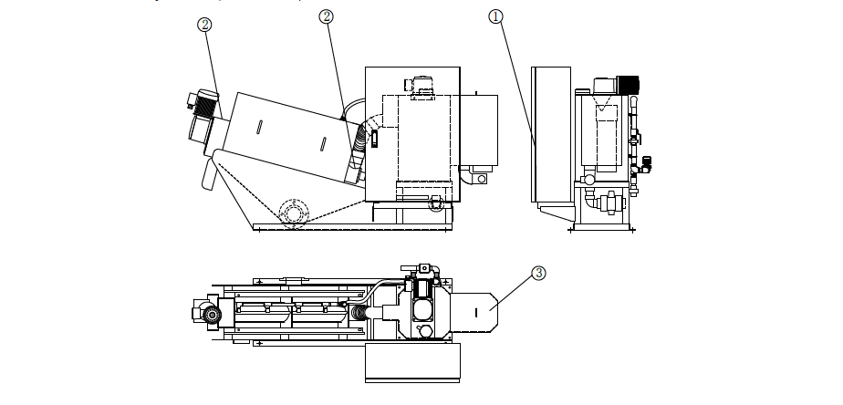
◆Safety Marks
To use the machine safely, there are Warnings, danger and indication signs on specific parts. Please fully understand the meaning of the following signs before use.
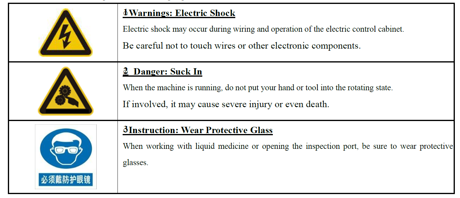 <Places with a Safety Label (JXDL-101)>
 II. Confirming Items
Upon receipt of the machine, please confirm the following:
In case the product is not ready, damaged or anything unsure, please contact our company or agent.
| Attention |
| --------- |
| ⚫ Check whether the product is consistent with the order.Products with inconsistent configuration models may cause injuries or machine damage. |
<Checking Items>
- Check the ordered machine and the present product of the nameplate engraved content is consistent.
- The machine may be damaged in transit.
So, when you entrust a transportation company to transport the machine, you should check whether there is any damage. In case of breakage, please take a picture of the damaged part and contact us or our agency immediately before acceptance.
※ In the case of delivery on site, the damage caused after the acceptance of the vehicle is not within the scope of our responsibility. - Bolts may loosen during transportation. Tighten the bolt again when it loosens.
- Check whether the parts listed on the shipping list are complete.
- Check whether the side of the machine is equipped with T hexagon wrench.
III. Production Introduction
◆Working Principle
The main body of the dehydrator screw is a kind of filter device which is composed of a fixed ring and a moving ring which are overlapped into a cylinder and the spiral axis runs through it. Because the inner diameter of the spiral axis is larger than that of the Movable ring, the rotation of the spiral axis drives the Movable ring to do circular motion to prevent blockage. The gap between the stationary ring and the moving ring decreases from concentration to dehydration along the direction of the cake outlet. After the sludge is concentrated by gravity in the concentration section, it is transported to the dehydration section, where forced dehydration is achieved under the internal pressure generated by the back-pressure plate at the outlet.
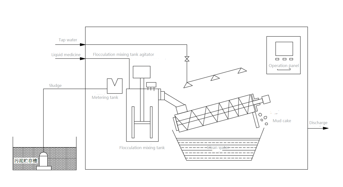
◆Basic Working Process
- Sludge is delivered to the sludge delivery port by a sludge delivery pump.
- After adjusting the flow rate through the metering tank, the sludge is transported to the flocculation mixing tank, which is fully stirred and mixed by a blender.
- After a large alum flower-like flocculate is formed by a blender, it is fed into the main body of the screw press.
- The alum flower-like flocculates are fed to the concentration section where gravity concentrates and moves toward the dehydration section.
- The gap between the Movable ring and the fixed ring in the dehydration section becomes narrow, and then the back-pressure plate at the outlet is adjusted to further pressure dehydration, and finally the mud cake is discharged.
◆Part Names
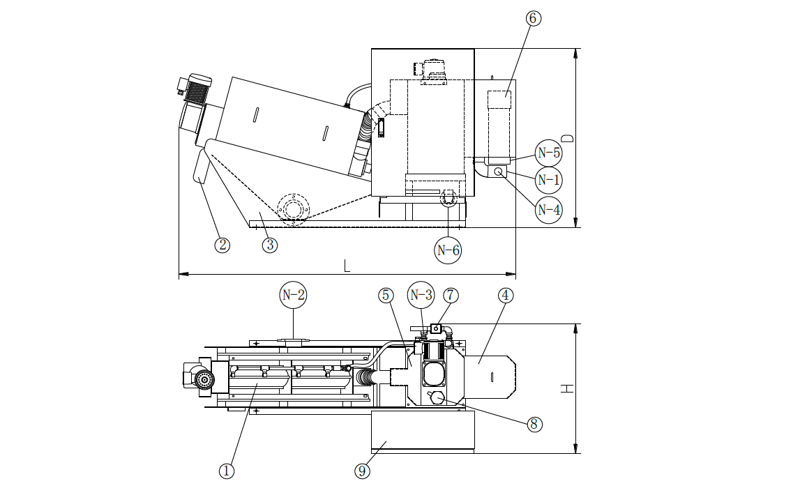
- The sludge in the sludge storage tank is transported to the metering tank by the sludge delivery pump.
- Transport to the metering tank sludge, through the metering transport to the flocculation mixing tank, the remaining sludge through the water level adjustment pipe back to the sludge storage tank.
- The sludge is transported to the flocculation mixing tank, the polymer flocculant is injected, and the sludge reacts with the polymer flocculant to form flocculation.
- The sludge through the mixing to form flocs, delivered to the main body of the stack.
- The sludge forming flocs is transported to the main body of the conch, and the conch concentration is transported to the dehydration department through gravity concentration.
- The gap between the moving ring and the fixed ring in the dehydration section is narrowed, and the filter cake is discharged after the back-pressure plate is pressurized for dehydration.
IV. Transportation · Installation
◆Working Environment
| Attention |
| --------- |
| Please follow the operating instructions when installing in case of machine failure. |
Working Environment
| Item | Environment |
| ---- | ----------- |
| Air Temperature | -10℃~+40℃ (no freeze) |
| Moisture | Max. 90%RH (no condense) |
| Height | Elevation below 1000m |
| Storage Temperature | 20℃~+65℃ (allowable temperature for short time transportation) |
| Noise | Below 70dB(A) |
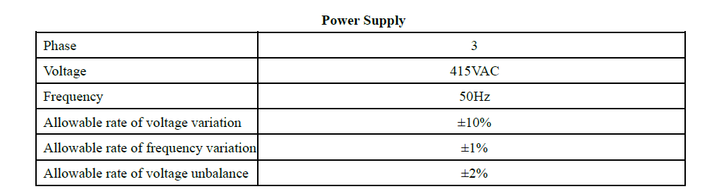
| Power supply | 3 phase- 415V-50Hz |
| Water supply pressure | 0.2~0.3MPa |
◆Transportation & Installation
| Warnings |
| -------- |
| ⚫The installation, transport and transfer should be conducted by professional companies.⚫When lifting or using a crane to lift the dehydrator, please allow qualified personnel to operate.⚫Fix the dehydrator with the specified bolt to prevent reverse or collision.⚫ When the dehydrator is placed on the stand, use the specified bolt to fasten the stand firmly to prevent upside down or bruising.⚫ For reference, please use nylon cable to lift and install the dehydrator.⚫ Please do not use forklifts to prevent upside-down or bruising.⚫ Please use a nylon cable to support the weight of the machine to prevent upside down or bruising.⚫ When lifting the dehydrator, keep it level to prevent reverse or bruise.⚫ When lifting the dehydrator, please keep the balance and lift slowly, in case of losing the center of gravity, upside down, falling and bumping.⚫ When lifting the dehydrator, please do not go under the dehydrator to avoid reverse or bruise. |
| Attention |
| --------- |
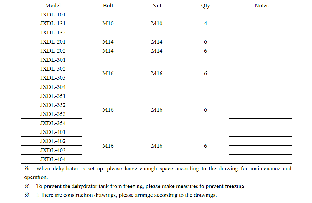
| ⚫ Please be careful when transportation and installation, do not shake strongly, in case of machine failure or damage.⚫ Please do not touch the spray pipe, piping, wire, operation plate, in case of machine failure or damage.⚫ Please do not use the hoisting rope to lift the main body of the winch in case of machine failure or damage.⚫ Please remove the cover when lifting the crane to prevent the machine from malfunction or damage.⚫ When installing, please ensure the maintenance space designated by our company. If there is not enough space, it will not only affect the maintenance work, but also cause bruising easily. |
< Table of Fixing Bolts >
 ◆Piping
| Attention |
| --------- |
| ⚫Do not tilt at the outlet of the filtrate piping to prevent the filtrate from spilling or contaminating the floor.⚫Prevent freezing countermeasures, in case of machine failure or damage |
◆Wirings
| Warnings |
| -------- |
| ⚫Please turn off the power to avoid electric shock during wiring operation⚫Please put the cover on after the wiring operation to prevent electric shock.⚫Wiring operation and inspection should be carried out by professionals to prevent electric shock.⚫Please do not damage the electric wires or put heavy things on them in case of electric shock or fire.⚫Please use the specified voltage in case of fire or machine failure.⚫Please implement earthing to prevent electric shock.⚫Please make sure to use the specified terminal post to prevent electric shock.⚫Be sure to equip the terminal post with insulation to prevent electric shock. |
- Connect the power supply to the specified terminal post according to the circuit drawing.
- Implement earthing operation. (D above ground)
- Identify the components that connect the terminal.
- When the flocculation mixing tank is placed separately, please connect the folding screw body and the operating plate.
 ◆External Wirings
| Warnings |
| -------- |
| ⚫ Please turn off the power to avoid electric shock during wiring operation⚫ Please put the cover on after the wiring operation to prevent electric shock.⚫ Wiring operation and inspection should be carried out by professionals to prevent electric shock.⚫ Please do not damage the electric wires or put heavy things on them in case of electric shock or fire.⚫ Please use the specified voltage in case of fire or machine failure.⚫ Please implement earthing to prevent electric shock.⚫ Please make sure to use the specified terminal post to prevent electric shock.⚫ Be sure to equip the terminal post with insulation to prevent electric shock. |
- External devices (polymer flocculant dosing pump, ferrous sulfate dosing pump, sludge conveying pump) are connected to the terminal post according to the circuit drawing.
- External devices need to be grounded.
- Identify the components that connect the terminal.
| Warnings |
| -------- |
| ⚫ During wiring operation, please turn off the power supply of the dehydrator operating panel and external power supply to prevent electric shock⚫ Please put the cover on after the wiring operation to prevent electric shock.⚫ Wiring operation and inspection should be carried out by professionals to prevent electric shock.⚫ Please do not damage the electric wires or put heavy things on them in case of electric shock or fire.⚫ Please do not use external signal beyond the power capacity, in case of fire, electric shock.⚫ Please do not use external signal specification of the voltage, in case of fire, electric shock.⚫ Please make sure to use the specified terminal post to prevent electric shock.⚫ Be sure to equip the terminal post with insulation to prevent electric shock. |
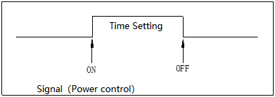
① Connect the external signal according to the terminal specified in the circuit drawing.
② Refer to the diagram below to connect the terminal.
 ③ The output power of external signal has no voltage contact. The contact capacity is as follows:
 ④ External signal input power, please confirm the contact capacity. Input power specifications are as follows:
 V. How to Use
The drawings and photos used in this manual are our standard specifications.
Therefore, the drawings and pictures of things may be different from the instructions.
◆Control Cabinet
The electric control cabinet is used to control and adjust the machine.
Please make sure that the following operation methods are used correctly on the basis of full understanding.
| Warnings |
| -------- |
| ⚫ The operation of the electric control cabinet must be carried out when the power supply is cut off. Avoid electric shock (except frequency converter). |
Control Panel
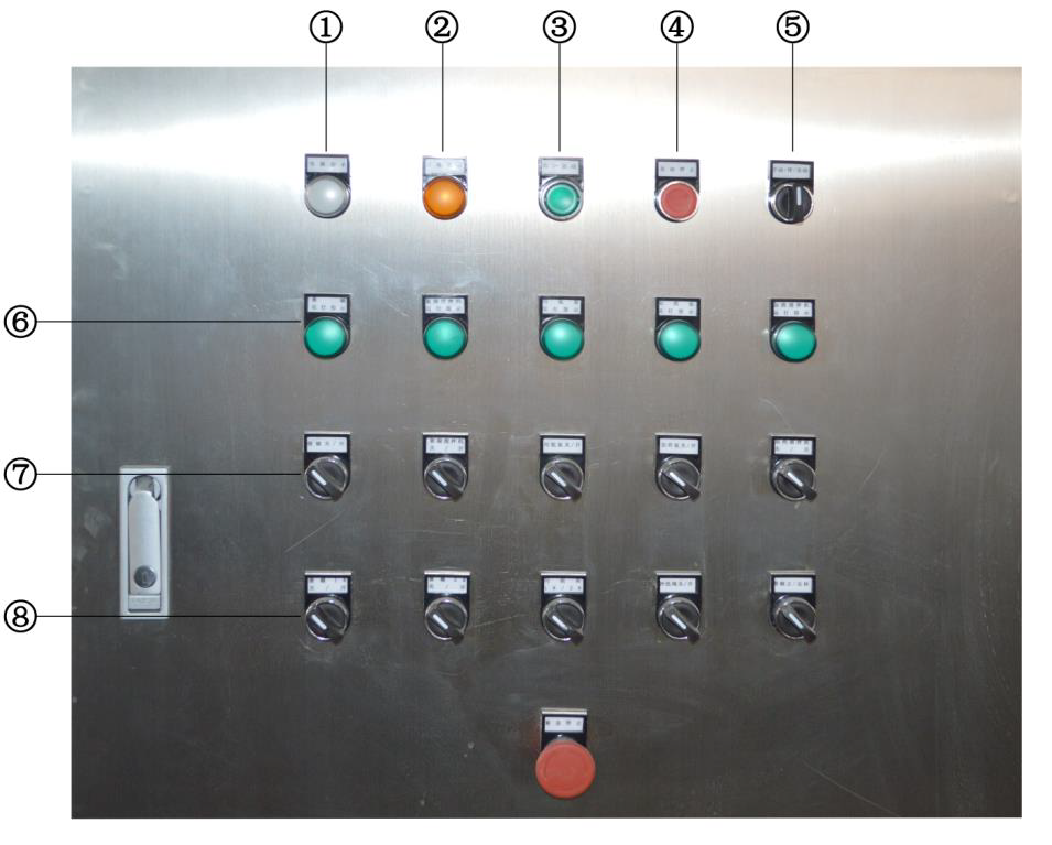
- Power indicator
The power indicator lights up when the machine is switched on. - Trouble lamp
The overload light will light up when the inverter is abnormal, or the motor is overloaded. - Auto start button
When the screw press is in the automatic state, press the auto start button, the indicator light will be on, and the equipment will start to run automatically. - Auto stop button
Press the auto stop button when the equipment needs to stop. - Manual- automatic switch button
Manual: the operation selection switch (7) of each machine is in an effective state, and each machine can operate independently.
Automation: the integrated control of each machine automatic operation. In this case, the operating selector switch (7) of each machine is in an invalid state. - Run indicator
When the stacking screw motor, mixing motor, dosing motor, sludge pump running the corresponding indicator lights will show green. - Option switch
Operation control switch of motor, mixing motor, dosing motor, sludge pump, etc. - Mushroom head stop button
Emergency stop: in case of emergency, press and hold this button to shut down the entire control system.
Inside the control cabinet
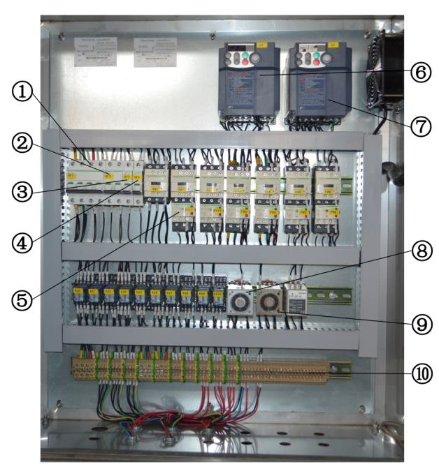 Description of each part
- Mains [ON--OFF]: the switch that controls the main power supply of the machine.
- Control line [ON--OFF]: the switch that controls the line power supply.
- Spray switch [ON--OFF]: the switch that controls the spray.
- Fan switch [ON--OFF]: the switch that controls the cooling fan
- AC contactor: controls on and off motor power supply
- Helical axis inverter: through the inverter to adjust the motor rotation speed of the helical axis, to prevent excessive current.
- Screw shaft running time delay timer: set the screw shaft running time delay timer.
- Spray operation timer: set the timer of the intermittent spray time of the main body of the stack screw.
- Receiving terminal: a terminal used for power connection.
◆Reducer
The machine uses a reducer to adjust the rotation speed of the screw shaft and the flocculating mixer.
| Warnings |
| -------- |
| ⚫ Please do not adjust the frequency converter when the machine and electric control cabinet are energized. It may cause electric shock; operation must be careful.⚫ Do not operate the electric control with wet hands to avoid electric shock.⚫ Please wear insulating shoes before operation. |
Transducer Appearance
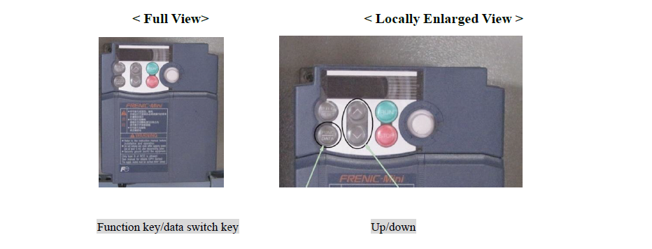 Regulation method of motor rotation speed
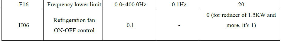
- Check the current set motor rotation speed
When the motor is running, the LED screen will display the current set motor rotation speed.
By pressing the function key/data switch key, the screen displayed on the LED screen will also switch.
(output frequency · setting frequency · output current · output voltage · output power, etc.) - Adjust the rotation speed of the motor
By pressing the function key/data switch key, switch to the screen with the set frequency.
Set proper rotation speed by pressing up and down keys.
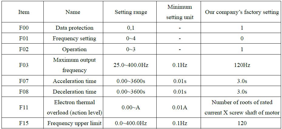
Our company’s factory setting
The company in the shipment according to the following table for initial setting.
For detailed usage, please refer to the instruction manual of reducer.
 ◆Timer
| Warnings |
| -------- |
| ⚫ Please cut off the power when setting the timer.When setting the timer, there may be a sudden start of the machine, which may cause the hand or tool to be involved and cause the person to be injured or the machine to be damaged. |
The machine is equipped with 3 timers
 The following is how to use the minimum timer when using the machine.
Please refer to the instructions of each timer for detailed usage.
Timers of screw shaft’s running time extending and spray solenoid valve circulation
Set the timer of spiral shaft · spray solenoid valve circulation
The operation of the timer is as follows:
<Timer Appearance>
Our company’s factory setting
D: Timers of screw shaft’s running time extending (Please do not change the Settings easily)
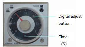 Timer of spray solenoid valve circulation

The red pointer shows the spray time and the green pointer shows the stop waiting time
Other parameters of this Omron time relay have been set according to the spraying requirements without adjustment. If the red pointer indicates 2, the spraying time is 2 minutes. With a green pointer indicating 3, the wait time is 30 minutes.
◆Valves
| Attention |
| --------- |
| ⚫ The valves must be restored to its original state after use, or it may be electrocuted due to water leakage. |
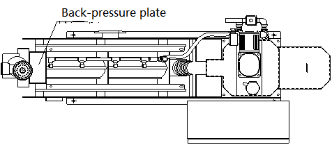
◆Back-pressure plate
Back-pressure plate is used to regulate the internal pressure of the screw body.
| Warnings |
| -------- |
| ⚫ When adjusting the back-pressure plate, be sure to switch the operation switch (cos-1) to "manual".When the operating switch (COS-1) is "automatic", if the machine is adjusted, the tool and hand may be involved. |
| Attentions |
| ---------- |
| ⚫ Do not adjust the back-pressure plate if there is no abnormality during routine inspection.⚫ Do not set back-pressure plate gap under 4mm.⚫ Excessive pressure in the spiral body will result in overloading.⚫ And will make the wear (Movable ring · screw shaft) premature wear.⚫ Do not overtighten the screws on the back plate. It may cause damage to screws. |
Positions of back-pressure plate and adjusting tools
 Adjustment of back-pressure plate
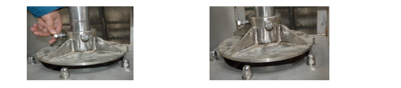
- Please make sure that the operating switch (COS-1) is "stop" and the screw body has stopped, then open the lid on top of the sludge discharge outlet.
- When the operation switch (COS-1) is turned to "manual", open the screw main body switch, stop when the bolt is turned directly above, and loosen the bolt.
- Loosen the bolt with a randomly matched t-hexagon wrench and adjust the position of the back-pressure plate.
- Determine the position of the back plate and tighten the bolt to fix it.
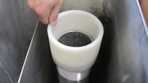
◆Level adjustment tube
Level adjustment tube is used to regulate the amount of mud
| Attention |
| --------- |
| ⚫ Please adjust the level adjustment pipe within the v-shaped weir.If the adjustment pipe is too tight or too loose, the machine will be damaged, so that wear products wear too quickly and speed up the replacement frequency. |
Position of level adjustment tube
When the amount of mud is rising
- Rotate to the left, adjust the tube to rise, the water level also rises.
- As the water level rises, the amount of water flowing through the weir increases, and so does the amount of mud.
When the amount of mud is declining
- Rotate to the right, adjust the tube to decline, the water level also declines.
- As the water level decline s, the amount of water flowing through the weir decreases, and so does the amount of mud.
Mud intake standard (weir scale)
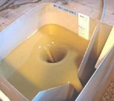 The surface scale can roughly reflect the current sludge transport.
The scale of weir scale can be used as a measuring standard.
◆Emergency Stop
| Warnings |
| -------- |
| ⚫ When the emergency stops button (EMS) is lifted, be sure to turn the operation switch to "stop".If the operating switch (COS-1) is not on the "stop", the operation of the machine may cause injuries when the emergency stop is removed. |
Please press the emergency button (EMS) immediately to stop the operation of the machine when something abnormal happens to the machine and endangers the operator.
※The "stop" of the operation mode switch (COS-1), the machine does not necessarily stop immediately due to the operation of the helical shaft delay time timer (tlr-2).In case of emergency, please be sure to use the emergency stop button (EMS) to stop the machine.
Recovery after emergency shutdown
- Please lift the emergency stop button.
- Operation mode switch (COS-1) to "stop".
- Rotate the emergency stop button (EMS) to the right to unlock.
- Select one of the "automatic" or "manual" operation mode switches (COS-1) and restart the machine.
VI. Start
| Warnings |
| -------- |
| ⚫ Do not operate the machine with the side cover open. There could be injuries.⚫ Do not put hands or objects into the mud pie outlet. It may cause injuries or machine damage.⚫ Do not put hands or objects into the flocculation tank while the machine is running. It may cause injuries or machine damage. |
◆Check before running
Check the piping inside the machine
- Check for loose connections between internal piping and external piping.
- Open the valve at the water supply outlet and check the supply piping for leaks.
- Open the maintenance valve of the dehydrator and check the pipe for water.
- Check that the valve is in the following on-off state.
 Check for foreign bodies
Check whether there is foreign matter such as packing material in metering tank and flocculation mixing tank
Check after power connection
| Warnings |
| -------- |
| ⚫ The inspection and confirmation of power connection must be carried out by professional technicians. In case of electric shock.⚫ Be sure to tighten the external terminal. In case of fire. |
- Please confirm whether the power in the main power supply and the electric control cabinet is cut off.
- Please tighten the bolts at the junction of the electric control cabinet.
- Please make sure that the operation mode switch (COS-1) on the electric control cabinet is adjusted to "stop".
- Please switch on the main power supply.
- Please use a multimeter to measure the voltage of the receiving terminal on the electronic control cabinet and check whether it conforms to the requirements.
- Please turn on the main power supply (ELCB-1) on the electric control cabinet.
- Please check whether the power indicator (WL-1) on the electric control cabinet is on.
- Please turn on the operation power supply (MCCB-C), control circuit power supply (CP-1) and spray power supply (CP-2) in the electric control cabinet.
Check the rotation direction of the motor
| Warnings |
| -------- |
| ⚫ Please have the wires wired and checked by a professional. In case of electric shock. |
- After completion of wiring, please be sure to check whether the wiring of the power supply phase is correct.
- Please cut off all the operation selector switch (CSL) in the electric control cabinet.
- Please switch the operation mode (COS-1) on the electronic control cabinet to manual.
- Please switch the screw axis on the electric control cabinet and the operation switch of the flocculation mixing tank mixer to the open position in turn and check the rotation direction of each motor. The correct rotation direction of each motor is shown as follows:
- Spiral axis: rotate counterclockwise from front to back of the outlet.
- Flocculation mixer: rotating clockwise from top to bottom.
- In case of motor reversal, please reverse connect the first (R) and third (T) of the power supply on the electric cabinet. Be sure to cut off the main power supply and the power supply in the electric control cabinet before operation.
◆Run Setting
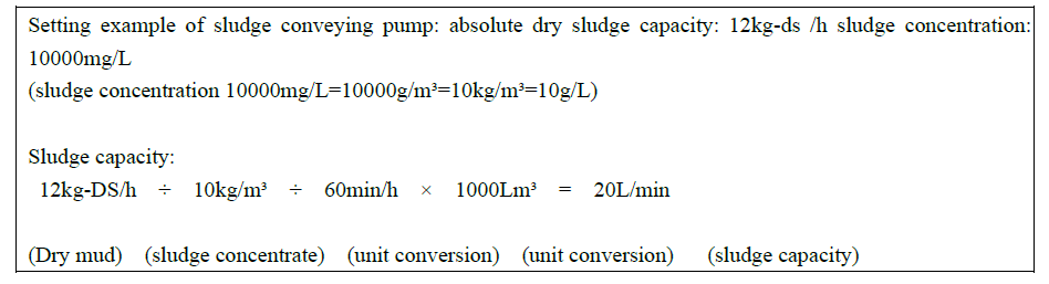
Sludge feed setting of sludge conveying pump
Please set the appropriate amount of mud according to the processing capacity of the machine.
In addition, the reaction time of polymerized iron is about 3 minutes, which should be considered when setting.
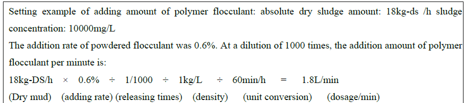
 Setting the dosage of polymer flocculant dosing pump
Please set the dosage of polymer flocculant according to the sludge treatment capacity and sludge concentration.
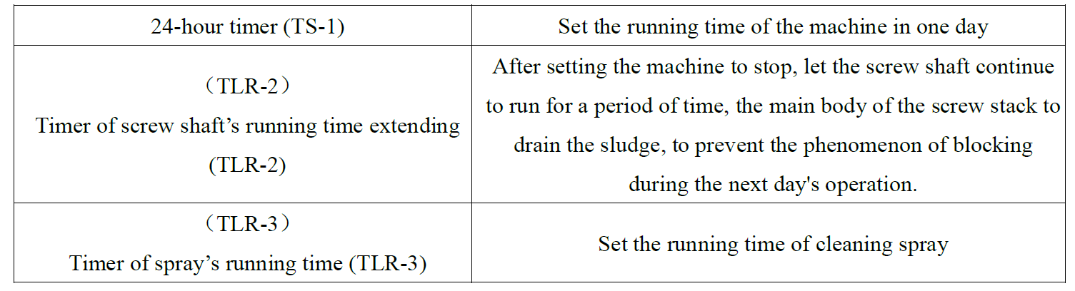
 Set the extension time of helical axis operation (TLR-2)
In the process of automatic operation, when the machine meets the stop condition and automatically stops, the running time of the screw shaft is prolonged by setting the timer to release the pressure in the main body.
Please set it roughly 5 minutes.
 Spray running time setting (TLR-3)
The spray "OFF" and "ON" for cleaning can be set separately.
The stop time is set by the green knob, and the run time is set by the red knob.
Please set it roughly to stop for 15 minutes/run for 25 seconds.
※In order to avoid the failure of the machine, please do not set the spray running time below 20 seconds.
The spray solenoid valve used by the machine adopts the energy saving mode of storage and recovery.
In the case of initial operation or re-operation after a long (5 days or more) shutdown, the charging voltage of the capacitor is reduced, and it takes about 30 seconds to start.
 Setting of rotation speed of screw shaft (INV-1)
Confirm the state of the filter cake, through the inverter to adjust the rotation speed.
The converter can be adjusted in the range of 20 ~ 120Hz.
※ After debugging, please do not adjust it easily unless there is abnormal phenomenon during daily or regular inspection.
 Setting of 24-hour timer (TS-1)
- Set the automatic running time.
- Set the present time.
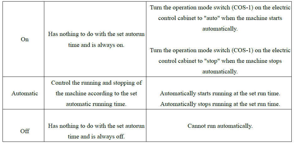
- The operation mode of the 24-hour timer (TS-1) is shown in the following table. Please use it according to the correct operation method.

 Adjust the moisture content of the filter cake
The moisture content and treatment capacity of the filter cake can be adjusted by "back-pressure plate" and "spiral shaft inverter (INV-1)".
- Setting of back-pressure plate gap
Reduce water content: by reducing the clearance of the back-pressure plate, increase the pressure in the main body of the conch, thereby reducing water content.
Improve water content: by increasing the clearance of the back-pressure plate, the pressure in the main body of the screw stack is reduced, and the water content is improved.
Notes: please do not adjust the clearance of back-pressure plate to less than 4mm.The smaller the gap between the back-pressure plate is, the lower the moisture content of the mud cake is, but it will also cause a great burden to the machine, leading to the vulnerable products (Movable ring, screw shaft) wear speed. - Set spiral axis inverter (INV-1)
Reduce water content: the frequency of the inverter down, the rotation speed of the screw shaft decreased, the processing capacity is also reduced. The concentration dewatering time of sludge in the main body of the conch is longer and the water content is reduced.
Increase water content: the frequency of the inverter is up regulated, the rotation speed of the screw shaft increases, and the processing capacity increases accordingly. The concentration and dehydration time of sludge in the main body of conch stack is shorter and the water content is higher.
Notes: after the rotation speed of the screw shaft is changed, each part of the machine should make corresponding changes
◆Formal Run
Please confirm the installation position of the machine and switch during the formal operation.
- Check whether there is polymer flocculant in the liquid medicine device, whether the liquid medicine device can operate normally, and whether it can be connected with the machine.
- Turn off all operation selector switches (CSL) on the electronic control cabinet.
- Put the operation mode switch (COS1) on the electric control cabinet in manual state, start the corresponding operation selection switch (CSL), check whether it can normally feed mud and dosing.
- Turn off the operation selector switch (CSL) on the electronic control cabinet.
- Check whether the 24-hour timer (TS-1) switch on the electric control cabinet has been placed in the "automatic" state and switch the operation mode switch (COS-1) on the electric control cabinet to "automatic" for automatic operation.
Please adjust the liquid level adjustment pipe (or intake pipe) and set the amount of mud.
Please adjust the dosing pump to set the dosage of polymer flocculant. - When the polymer flocculant and sludge react in the flocculation mixing tank, check whether the ideal alum flower is formed. The ideal alum flower diameter is approximately 5 ~ 10mm.If the ideal alum flower cannot be formed, the rotation speed of the mixer is one of the reasons. The speed of rotation can be adjusted by the inverter (INV-2).
 Alum flower-like flocculates into the main body of the stack, after processing the formation of mud cake from the mud cake outlet. The pressure in the main body of the screw stack gradually increases with the inflow of sludge, so it takes a certain amount of time (about 60 minutes) to form the mud cake.
VII. Automatic Run
The machine can realize automatic unattended operation through the setting of 24-hour timer (TS-1).
| Warnings |
| -------- |
| ⚫ In the case of automatic operation, do not touch any movable parts even if the machine is in standby mode.To prevent the machine from restarting automatically when the moving parts involved in the cause of injury. |
- Please set the 24-hour timer (TS-1) mode and the running time of one day.
- Please check for any abnormal external signals in case of failure of the liquid device and reduction of the level of the sludge storage tank.
- Please switch the operation mode of the electric control cabinet (COS-1) to auto mode.
When the 24-hour timer (ts-1) mode is "on", the machine runs independent of the time set by the timer. Set to "auto," the machine runs according to the timer.
VIII. Manual Run
When checking the running condition of the pump or motor and the dehydrator needs to be stopped for maintenance for a long time, the operation selection switch (CSL) shall be adjusted manually for various inspection and maintenance.
| Attention |
| --------- |
| ⚫ In the state of manual operation, the level sensor cannot be automatically controlled. Do not use manual operation except for checking pump and motor operation. To prevent sludge from overflowing from the mixing tank and causing damage to the machine |
- Please cut off all the operation selector switches (CSL) of the electric control cabinet.
- Please switch the operation mode switch (COS-1) on the electronic control cabinet to manual.
- Please turn on the operation selection switch (CSL) to check whether each machine can operate independently.
※Never leave the machine idling while checking the operation of the pump.
In case of wearing parts of a wear, shorten the service life of the product.
IX. Running Adjustment
| Warnings |
| -------- |
| ⚫ Please do not touch the inside of the electric control cabinet with wet hands. In case of electric shock.⚫ Please wear insulating shoes for operation. In case of electric shock.⚫ Please adjust the frequency converter when the power is off. In case of electric shock.⚫ Adjust the back-pressure plate when the machine is stopped to prevent hand or tool involvement. |
| Attention |
| --------- |
| ⚫ Do not set the clearance of back-pressure plate below 4mm.To prevent excessive pressure in the main body of the winch from overloading the machine, and to prevent wearing parts (Movable ring · screw shaft) to shorten the service period. |
◆About running adjustment
After the initial commissioning of the machine, there is no need for any other adjustment except liquid supplement.
Please check the residue of the liquid regularly.
When the sludge concentration changes significantly (±10% or more), the shape of the sludge will change greatly. Please adjust the mud intake, the water content of the filter cake and the treatment capacity.
Adjustment of sludge concentration under changing conditions
The sludge concentration may affect the treatment capacity in the case of variation. Please adjust it by the following methods.
- to improve the handling capacity, speed up the rotation speed of the helical shaft drive motor, and increase the mud intake through the liquid level adjustment tube.
- to reduce the handling capacity, slow down the rotation speed of the helical shaft drive motor and reduce the amount of mud entering through the liquid level adjustment tube.
※ if you do not adjust the back-pressure plate clearance, blindly increase the amount of treatment, may cause excessive accumulation of sludge in the main screw body. In this case, not only will lead to motor overload, but also will make the moving ring, spiral shaft and other wearing parts wear faster.
Adjustment under the circumstance that moisture content changes high
The decrease of sludge concentration will lead to the decrease of the number of solids added, which will lead to the increase of water content. As the number of solids added decreased, the pressure in the main body of the screw stack decreased, and the dehydration performance decreased.
In this case, the amount of mud added is increased to achieve the effect of increasing the number of solids added.
※Under the condition of increased mud intake, please do not let the liquid level be higher than the high level (H position) in the flocculant mixing tank and ensure the continuity of dehydration through appropriate adjustment.
※In the case of increased sludge inflow, if the sludge concentration becomes higher, it will exceed the normal treatment capacity of the main body of the conch, and the sludge level will often be higher than the motor level (H position) of the flocculation mixing tank, which will cause the following symptoms, so the sludge concentration should be checked regularly.
- the moisture content and treatment capacity of the filter cake are unstable.
- the sludge quantity for the main body of the screw stack is unstable.
- foreign body mixed on the electrode caused the pump to stop
- when the pump is in regular clearance operation, its service life will be reduced.
Wear and tear of machine wearing parts will lead to the original performance and efficiency of the machine cannot give full play.
If there is a decrease in the treatment capacity, water content rise, through the adjustment cannot be improved, please contact our company.
X. Maintenance & Inspection
| Warnings |
| -------- |
| ⚫ Be sure to turn off the power when cleaning the screw bodyTo avoid being sucked in the machine and causing human injuries |
| Attention |
| --------- |
| ⚫ When the machine is not running within 1 week (2-3 days for sludge that is easy to dry), be sure to empty all the sludge in the main body of the screw stack.⚫ The sludge in the machine remains in the main body of the winch and the machine does not run for 1 week (2-3 days for the sludge that is easy to dry). When the machine is started again, the sludge that has been dried will cause damage to the machine. |
◆Check and Abnormal Response
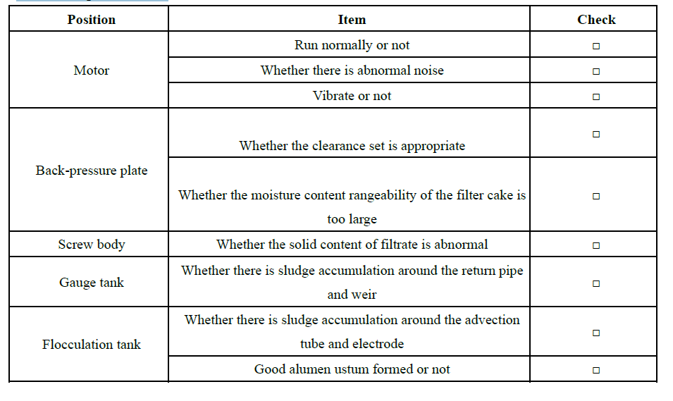
The manual contains a form for routine inspection and regular inspection. Please use it wisely.
In addition, the motor, pump, frequency converter, etc., in the inspection or abnormal conditions, please refer to the operation manual of each machine.
Routine Inspection Items
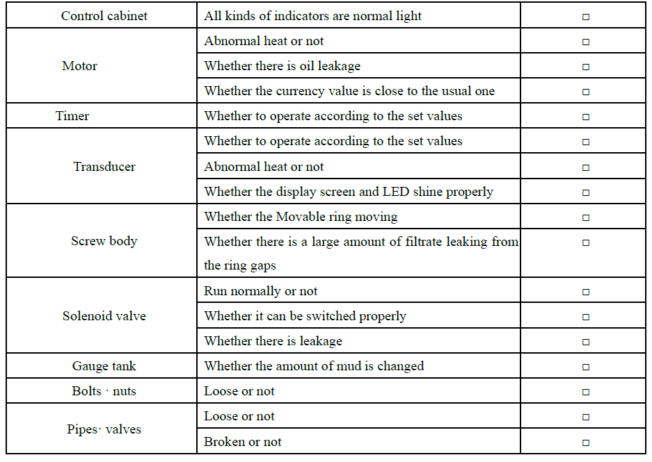
 Regular Inspection Items

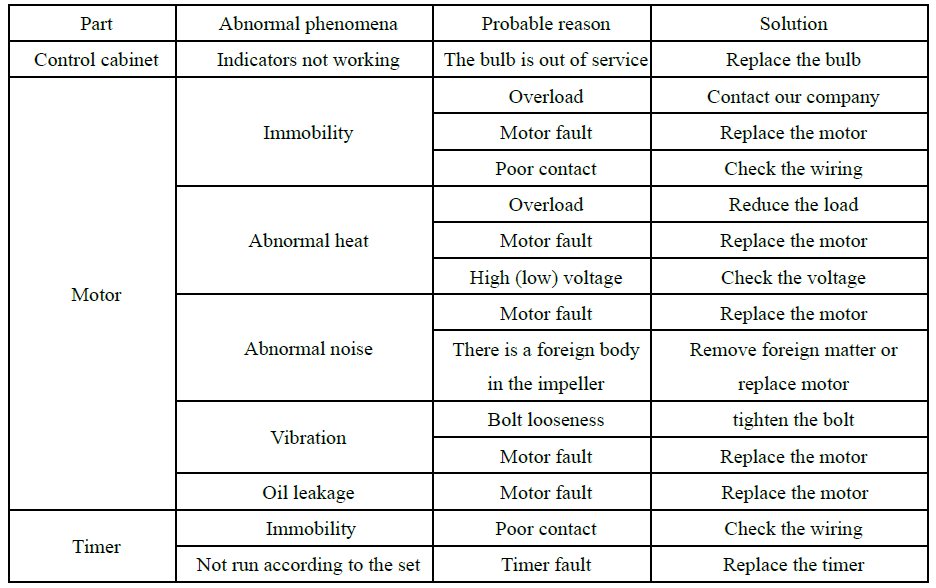
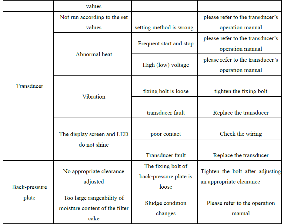
 Handlings of exceptions
 ◆Cautions about Longtime Shutdown
When the machine shut down for more than 1 week (2-3 days for sludge that is easy to dry)
- If the machine is shut down for more than one week, to protect the machine, be sure to do the following:
To prevent the sludge in the tank from rotting and drying, the sludge in the flocculation mixing tank should be emptied from the cleaning outlet and washed with water in the tank.
※To drain the sludge from the mixing tank, leave the mixer in the mixing mode and open the ball valve under the mixing tank. In this way the sludge in the tank can be emptied smoothly. - Leave the back-pressure plate open to the maximum and allow the screw shaft inside the main body to run manually for 1 hour. After all the sludge is discharged from the main body, clean with water.
- Turn off the main power in the electric control cabinet.
When the machine shut down for more than 3 months
If more than 3 months of downtime, in addition to the above measures, following work must be carried out too:
- To prevent the end of the electric control cabinet from rusting, it is necessary to close the door of the electric control cabinet and keep the indoor air unobstructed.
- To prevent the electromagnetic relays in the electric control cabinet from rusting, the machine should be operated manually every 3 months.
XI. Malfunction
When the failure indicator light (OL-1) on the electric control cabinet is on, please confirm the following items again before preparing for consultation or requiring repair.
| Warnings |
| -------- |
| ⚫ When lifting the overload relay, first turn the operation mode switch (COS) on the electric control cabinet to "stop".In case the overload relay is released, the machine operator may be involved and get injured. |
| Attention |
| --------- |
| ⚫ In case of machine failure, please stop running the machine and contact our company or agent.Continuing to run the machine in the event of a failure may cause more damage. |
◆Thermal Overload Relay is Disconnected
Motor or pump in the case of overload, the machine in electric control cabinet of the thermal overload relay will disconnect, to start the protection function, relay at the time of disconnection, the machine will stop, the corresponding parts of the thermal overload relay warning lights and electric control cabinet of trouble light (OL - 0) will light up, in this case, ruled out why the machine overload, lift off state.
If the thermal overload relay disconnects frequently, please stop and contact the company or the agent. If the machine continues to be forced to run, severe damage may be caused.
Release method of relay disconnection
- Set the operation mode switch (COS-1) on the electric control cabinet to the stop position.
- Cut off the main power supply on the electric control cabinet (ELCB-1).
- Eliminate the cause of the machine thermal overload relay disconnection.
- Press the white button on the thermal overload relay to disconnect the relay.
※When the temperature of the thermal overload relay is too high, sometimes the disconnection of the relay cannot be lifted immediately. In this case, it is necessary to cool the thermal overload relay for a period before trying. - Restart the operation mode switch on the electric control cabinet (COS-1)
◆Error Signals on Transducer
When the inverter (INV) detects an abnormal condition, the inverter's LCD screen will display an error signal and the machine will automatically stop running. When the contents displayed on the display screen are not consistent with the usual, please refer to the inverter instruction manual or consult our company.
Recovery method after an error signal occurs
- Adjust the operation mode switch (COS-1) on the electric control cabinet to "stop".
- Eliminate the cause of the error signal.
- Press the program key/reset key of inverter (INV).
- Adjust the running mode switch (COS-1) to "run" and restart the machine.
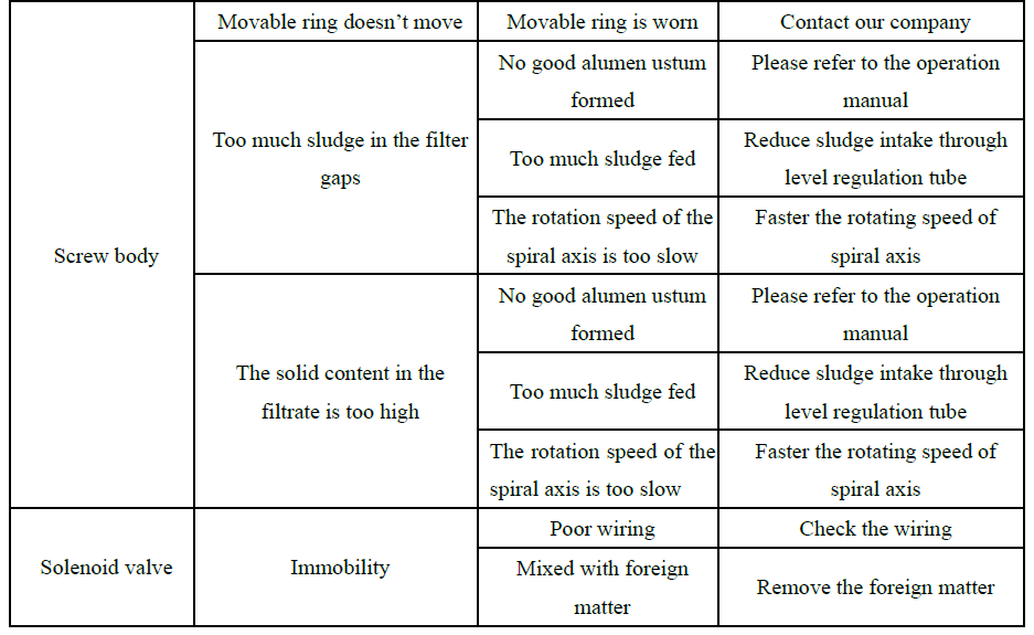
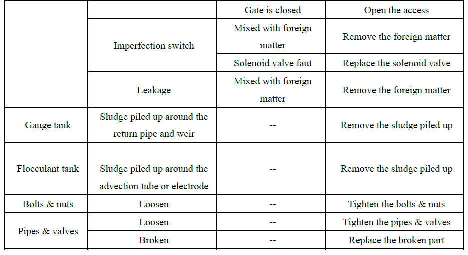
◆Confirmation before Consultation
Before consulting or requesting repairs, please reconfirm the following frequent problems. After confirmation, if the machine is not working properly, please consult our company or agency.
﹤Frequent Asked Questions﹥
Can't run automatically
Under the condition that automatic operation is set, and the operation mode is switched to automatic, it still cannot operate automatically. Please confirm the following:
- Is the manual switch of the 24-hour timer (ts-1) automatic?
- Are there any abnormalities in the dosing device and sludge storage tank?
- Is the thermal overload disconnected?
- Does the emergency stop button (EMS) pressed?
※In the case of non-standard production, it may not follow the above steps completely.
If the above method still cannot be solved after implementation, please confirm in more details.
- Before inspection, please be sure to adjust the operation mode switch (COS-1) to the "stop", each operation selection switch (CSL) to the "close" position, but also check the valve state is normal.
- When the total power of the machine (ELCB1) turned on, the power indicator (WL-1) will be lit, each inverter (INV) LED screen will be lit up. When the light and screen are not on, it may be caused by the lack of power supply of the machine, the life of the light, and the failure of the converter. Therefore, when switching or wiring operations, be sure to cut off the power supply, and ask professional technicians to operate.
- When the operating power supply (MCCB-C) of the electric control cabinet of the machine is connected, the fault indicator (ol-0) is not on. Even if the emergency stops button (EMS) is pressed, the fault indicator does not light up. In addition, the fault light will not be on when receiving the fault signal of the liquid device. If the failure indicator (OL-0) lights up, it may be caused by the following reasons.
- The drive motor of the screw shaft is overloaded
- Overload of polymer flocculant dosing pump
- Overload of sludge conveying pump
- An error occurred in the frequency converter of the motor driven by screw shaft
- An error occurred in the converter of the mixing tank stirring motor
In case of recovery, please eliminate the cause of the fault and remove the short-circuit fault.
- The 24-hour timer (TS-1) is in or automatic state. Even in the automatic state, if the current time is outside the time range set by the operation, the machine is in the automatic operation standby state, the machine cannot run. If you need to run the machine immediately, you must change the running time set on the timer.
- Do not let the sludge storage tank sludge below the lowest level. If the sludge level is below the lowest level, cut off the main power supply (ELCB-1) and the operating power supply (MCCB-C).Before starting the dehydrator, check whether the liquid level of the sludge storage tank is in the normal position.
- Keep the timer of the delayed screw shaft running in the energized state. Check that the power indicator on the front of the timer is on. If the indicator light is not on, it may be due to timer failure or faulty wiring. When switching or wiring operations, be sure to cut off the power supply, and ask a professional to operate.
After all the above work is checked, you can switch the operation mode (COS-1) to the automatic position to allow the machine to run automatically. The automatic operation cannot be carried out after all inspections, please contact our company.
The sludge did not enter the flocculation tank
- Sludge pump is not working.
If the pump is not working, please contact the pump manufacturer. - Is there residual air in the sludge pump?
The failure of the level controller for sludge storage makes the level controller unable to operate normally, and the sludge cannot be transported normally due to the suction of air in the sludge conveying pump. Please check the sludge storage tank. - Is the sludge pump clogged?
Turn off the main power of the machine (elcb-1) and check whether the sludge transfer pump is blocked. - Is the impeller of the sludge pump worn?
Although the pump is running, the sludge cannot be fully transported, which may be caused by wear of the impeller. If this happens, please contact the pump provider. - Is the sludge in the flocculation tank too full (higher than the electrode level)?
The flocculation mixing tank sludge is too full, appear mud into the state of too much.
In this case, by adjusting the level adjustment tube to reduce the amount of mud into and readjust the dosage of drugs.
The flocculation tank is in the state of full water and will recover after a period. This will cause the pump in the intermittent working state, shorten the service life of the pump. Therefore, it is important to adjust the sludge throughput and dosage to an optimal value.
- The foreign body attached to the electrode of the flocculation mixing tank makes it unable to operate normally.
If a foreign body is attached to the electrode rod and causes a short circuit, it will be wrongly judged to be running in a state of full water. Please remove the foreign body. - Are the valves in the sludge line closed or blocked?
- Check valve on/off condition and line for blockage.
The filter cake cannot be discharged
- Does the flocculation tank have sludge flowing into the main body of the conch?
Check whether the pipe connecting the flocculation mixing tank and the main body of the screw body is blocked. - Is the size of the alum flower formed in the flocculation mixing tank inappropriate?
When alum flower cannot form or cannot form completely, solid substance will fall from the main body of the gap in the leakage, resulting in a decrease in the recovery of solid substance, the discharge of the filter cake to reduce, or even no mud cake out. Please adjust allow the sludge to form the appropriate alum flower. - Is the clearance of the back-pressure plate adequate?
When the clearance of back-pressure plate is 0mm (fully closed), the mud cake cannot be discharged from the outlet.
Please set the proper back-pressure plate clearance. - Is the drive motor of the screw shaft operating normally?
Please check whether the drive motor of the screw shaft is running normally.
If the motor does not work properly, it may be due to the motor failure, please immediately stop the operation of the machine, consult our company or agency. - Is the motor driven by screw shaft rotating in the correct direction?
In the exchange of the main screw stack, if the screw shaft drive motor wiring errors, will cause the motor to reverse.
Sludge cannot be discharged during reversal, which may cause damage to the machine. Therefore, if the motor is reversed, please cut off the power and check the wiring condition.
The spray won't come out
- Is the valve closed?
Check that valves in all supply lines are open. - Is there a garbage jam at the spray head?
Remove the spray head and remove the garbage. - Whether the "running time (ON)" of the spray running time timer (tlr-3) is at the position of 0.
The "run time (ON)" setting knob (red pointer) is set to more than 20 seconds. - Is the spray solenoid valve in normal operation?
Check whether the spray solenoid valve is in normal operation. Failure to operate normally may be due to the solenoid valve failure, please consult our company or agency. - Is the spray power on?
To protect the spray solenoid valve, the solenoid valve is set with a switch, if the switch is not opened, the solenoid valve will not start.
The moisture content of the filter cake is too high (in the case of small alumen ustum)
- Is the sludge too thick?
When the sludge concentration becomes thin, the ratio of the solid substance of the sludge and the amount of medicine added is out of balance, and the suitable alum flower cannot be formed. At this time, combined with the processing capacity of the machine to reduce the amount of mud and thus reduce the amount of solid material input. - Is the sludge PH appropriate?
If the PH value is not appropriate, the polymer flocculant may not be able to give full play to its performance.
Determine the appropriate PH range for the polymer flocculant used and adjust the PH of the sludge to an appropriate value. In addition, the drugs used will reduce the PH value of sludge, resulting in the performance of polymer flocculant cannot be fully played, in this case, to minimize the use of drugs to reduce the PH value of sludge. - Has the concentration of polymer flocculant changed?
As soon as the concentration of polymer flocculant solution changes, the balance between solids and drug dosage rate in the sludge is destroyed, resulting in the inability to form a suitable alum flower.
When soaking the medicine manually, please confirm the dosage of polymer flocculant and the dosage of diluted water.
When using the automatic infusion machine, please make sure that the set value is consistent with the dosage. - Is the outflow of high - resolution flocculant appropriate?
Please stop the operation of the machine and remove all the sludge from the flocculation tank.
The polymer flocculant dosing pump is started under manual operation mode to check whether the discharge volume of the pump is consistent with the performance curve of the pump. If the result is low or no discharge, please check the following.
Whether there is foreign body blocking in the pipeline.
Is there any liquid medicine in the bubble tank?
Whether the vulnerable parts of the pump are damaged. - Is there any garbage around the level adjustment pipe and weir in the metering tank?
If there is garbage around the level adjustment pipe and weir, this will affect the return of sludge. The proportion of the solid substance in the sludge and the amount of medicine added will be out of balance, resulting in the inability to form a suitable alum flower. At this time, please clean the level adjustment tube.
If the above measures still cannot solve the problem, please choose polymer flocculant again.
Please contact our company, agent or polymer flocculant sales company.
The moisture content of the filter cake is too high (in the case of large alumen ustum)
- Has the sludge thinned out?
When the sludge concentration becomes thin, the ratio of the solid substance of the sludge and the amount of medicine added is out of balance, and the suitable alum flower cannot be formed. At this time, combined with the processing capacity of the machine to increase the amount of mud to increase the amount of solid material input. - Has the concentration of polymer flocculant changed?
As soon as the concentration of polymer flocculant solution changes, the balance between the solid substance in the sludge and the amount of drug additive is destroyed, resulting in the failure to form a suitable alum flower.
When manual infusion is used, please confirm the dosage of polymer flocculant and the dosage of diluted water.
When using the automatic infusion machine, please confirm whether the set value is consistent with the dosage.
If the polymer flocculant is added too much, the following symptoms may occur. When alum is in its proper state, check to see if the following symptoms have improved.
Is there a high viscosity sludge around the advection tube?
·Is there a high viscosity sludge in the clearance of the ring of the conch body?
·Is the water consumption function of the main body good?
·Is the filtrate viscous?
·If the moisture content of the filter cake decreases, does the load (current value) of the motor become higher? - Is there any garbage around the metering tank?
When garbage is attached around the weir, the amount of sludge flowing into the flocculation mixing tank will be reduced, and the proportion of solid substance and drug dosage in the sludge will be out of balance, which may cause the alum flower to become larger. In this case, please clean the weir around.
※If the above measures still cannot solve the problem, please choose polymer flocculant again.
Please contact our company, agent or polymer flocculant sales company.
XII. Consumables
In the process of using the machine, some parts will be worn, after a certain period, it is necessary to replace the parts.
We hereby declare in advance, even in the warranty period, the replacement of consumables will be charged.
| Attention |
| --------- |
| ⚫ Because of the change of sludge concentration, the moisture content of mud cake and sludge treatment capacity will change greatlyCauses the machine to exceed its processing capacity. Please readjust the machine.Always in the state of overload movement, may cause the main body of the stacking screw sludge jam, screw shaft drive motor overload, vulnerable products (Movable ring, screw shaft) abnormal wear. |
Replacement standard for consumables
The machine will not be able to give full play to its ability with the wear of the moving ring and the screw shaft. Please refer to the table below to confirm the running time of the machine.

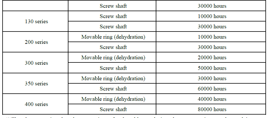 ※The above-mentioned replacement time of vulnerable goods is only an approximate value and is not a guarantee period for the service life of vulnerable goods. After the replacement period and do not need to replace the situation also has, the main impact on the service life is the use method and use conditions.
※The replacement period is the data obtained from certain experimental conditions. In the actual operation process, changes in relevant conditions (sludge type, sludge shape, treatment capacity, operation adjustment state, condition of supporting facilities) will cause changes in the replacement period.
About after-sales service
- When you need repair service, please inform us of the model number and manufacturing number of the machine engraved on the nameplate.
- Even in the warranty period, the items beyond the warranty scope are all paid services.
- After the warranty period, provide paid service according to the needs of customers by maintaining the machine function.
- When the machine is repaired, the reusable products will be replaced, and we will recycle them.
XIII. Warranty
- Guarantee object
The warranty object is the machine specified in the name of the machine on this warranty. - Guarantee period
12 months after the date of shipment. Over 12 months is not covered by the warranty.
The following are the storage conditions before use:
- Set in the building without leakage, leakage, namely indoor setting.
- No abnormal high-temperature, great temperature difference, extreme humidity and no dew.
(temperature range: -10℃ ~ 40℃ humidity range: less than 85%)
No corrosive gas, no salt damage and other major materials affecting the machine. - Take corresponding measures not to affect the machine when the surrounding construction.
- Do not place objects on the machine or put objects against the machine.
- Do not connect to the power supply before use, do not store water and sludge.
- Custody after delivery is your responsibility.
- Guarantee range
- The warranty scope is limited to the company's manufacturing scope only.
- During the warranty period, normal installation and operation shall be carried out according to the operating instructions. If the unit still fails to operate normally, our company will come to repair it after finding out the reason.
- In principle, our company is only responsible for loading the machine to the designated place, from unloading to installation by your company.
- Extra precautions
Even within the warranty period, if the following items are not within the warranty scope, by the customer to bear the repair costs.
- Failure caused by customer's random disassembly and transformation.
- Customer in use beyond the scope of specifications (certain specifications, standard specifications, etc.).
- Damage to the machine caused by forced lifting and other impact when moving in or moving the machine.
- Failure caused by customer's negligence in use, improper storage, maintenance, safety management and other reasons unrelated to the company.
- Failure caused using an impure component or an out-of-specification consuming component.
- A malfunction caused by repair at a factory other than our own or our designated factory.
- Natural fading of painted parts.
- Malfunction caused by fire, salt, poisonous gas and other natural disasters.
- Exchange of the following consuming parts
Movable ring, screw shaft, screw nut class, bearing, solenoid valve, side baffle, sticker class, operation panel display lamp, fuse etc.
Except for the above-mentioned item, the cause is unknown and shall be decided by consultation between the two parties.
This section provides comprehensive documentation for all products in the Sludge Dewatering category. Please select a specific product below to view its detailed manual.
Available Products
SS316-404-Sludge Dewatering Press
SS304-404-Sludge Dewatering Press
SS316-403-Sludge Dewatering Press
SS304-403-Sludge Dewatering Press
SS316-402-Sludge Dewatering Press
SS304-402-Sludge Dewatering Press
SS316-401-Sludge Dewatering Press
SS304-401-Sludge Dewatering Press
SS316-354-Sludge Dewatering Press
SS304-354-Sludge Dewatering Press
SS316-353-Sludge Dewatering Press
SS304-353-Sludge Dewatering Press
SS316-352-Sludge Dewatering Press
SS304-352-Sludge Dewatering Press
SS316-351-Sludge Dewatering Press
SS304-351-Sludge Dewatering Press
SS316-304-Sludge Dewatering Press
SS304-304-Sludge Dewatering Press
SS316-303-Sludge Dewatering Press
SS304-303-Sludge Dewatering Press
SS316-302-Sludge Dewatering Press
SS304-302-Sludge Dewatering Press
SS316-301-Sludge Dewatering Press
SS304-301-Sludge Dewatering Press
SS316-253-Sludge Dewatering Press
SS304-253-Sludge Dewatering Press
SS316-252-Sludge Dewatering Press
SS304-252-Sludge Dewatering Press
SS316-251-Sludge Dewatering Press
SS304-251-Sludge Dewatering Press
SS316-202-Sludge Dewatering Press
SS304-202-Sludge Dewatering Press
SS316-201-Sludge Dewatering Press
SS304-201-Sludge Dewatering Press
SS304-132-Sludge Dewatering Press
SS316-132-Sludge Dewatering Press
SS316-131-Sludge Dewatering Press
SS304-131-Sludge Dewatering Press
Need Help?
If you need additional assistance with any product in this category, please contact our support team.